4.5. Built-in PLC Function
The PLC ladder logic can be created and downloaded using the Gefran PC Tool Congurator software.
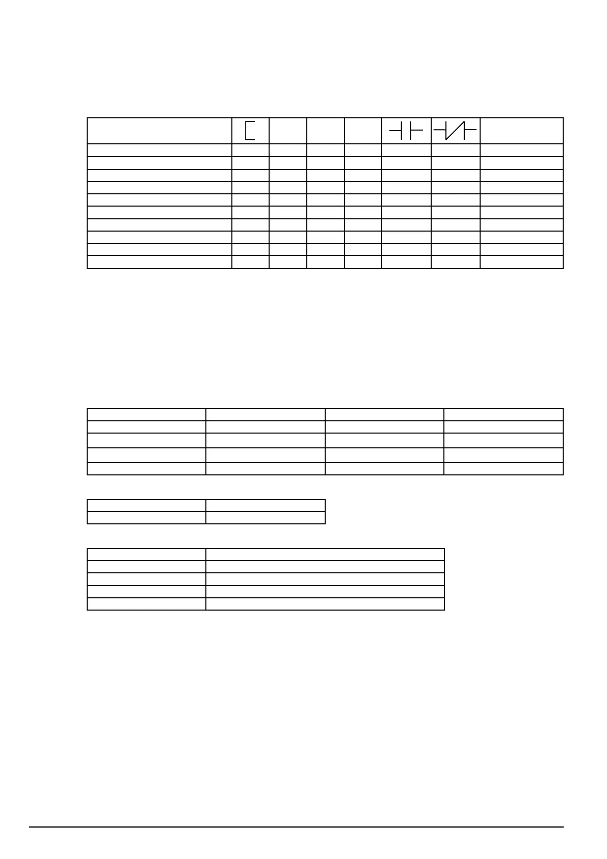
4.5.1. Basic Command
▲ ▼
P
NO / NC
Inputs I i I1~I8 / i1~i8
Outputs Q Q Q Q Q q Q1~Q2 / q1~q2
Auxiliary command M M M M M m M1~MF / m1~mF
Special registers V1~V7
Counter function C C c C1~C8 / c1~c8
Timer function T T t T1~T8 / t1~t8
Analog comparison function G G g G1~G8 / g1~g8
Operation control function F F f F1~F8 / f1~f8
summation and subtraction function AS AS1~4
Multiplication and division function MD MD1~4
Description of registers
V1: Set frequency Range: 0.1~1200.0Hz
V2: Operation frequency Range: 0.1~1200.0Hz
V3: AI1 input value Range: 0~1000
V4: AI2 input value Range: 0~1000
V5: Keypad input value Range: 0~1000
V6: Operation current Range: 0.1~999.9A
V7: Torque value Range: 0.1~200.0%
Command Upper Differential Lower Differential Other command symbol
Differential command D d
SET command
▲
RESET command
▼
P command P
Command “ “
Short circuit “--”
Connection symbol Definition
─
Connect components on the left and right side
┴
Connects components on the left , right and top side
┼
Connects components on the left , right , top and bottom side
┬
Connects components on the left , right and bottom side
286 VDI100 • Instruction manual

 Loading...


