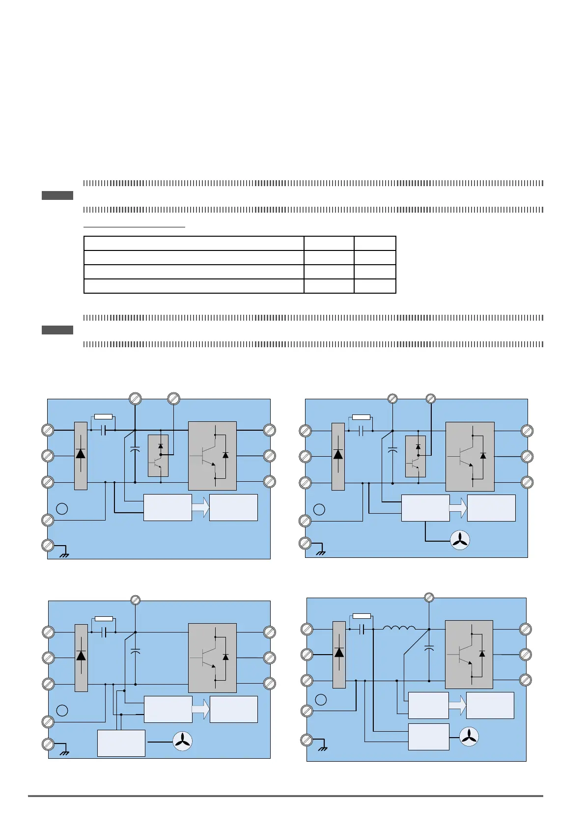
3.11. Input/OutputPowerSectionBlockDiagram
The following diagrams 1 - 5 show the basic conguration of the power sections for the range of power and
input voltages. This is shown for reference only and is not a detailed description.
DC power supply
All the VDI100 ranges below can be power supply from DC link:
- 230V 3ph up to 22kW,
- 400V 3ph up to 90kW
Note ! On VDI100 above 90kW, DC bus cannot be used.
DClinkconnectionterminals:
Range Terminals Diagrams
VDI100 230V 3ph up to 18.5kW and VDI100 400V 3ph up to 30kW B1/P and (-) 1 and 2
VDI100 230V 3ph 22kW and VDI100 400V 3ph 37-55kW (+) and (-) 3
VDI100 400V 3ph 75-90kW P and N 4
Note ! For DC power supply, fuses and DC pre-charge circuit must be provided externally.
1: 230V Class: 0.75 kW / 400V Class: 0.75 ~ 1.5 kW 2: 230V Class: 1.5 ~ 18.5 kW / 400V Class: 2.2 ~ 30 kW
L1/R
L2/S
L3/T
U/T1
V/T2
W/T3
B1/P
B2
Main Power Secon
+
-
-
Control
Circuit
DC /DC
Converter
E
L1/R
L2/S
L3/T
U/T1
V/T2
W/T3
B1/P
B2
Main Power Secon
+
-
Control
Circuit
Cooling Fan
DC /DC
Converter
-
E
3: 230V Class: 22 kW / 400V Class: 37 ~ 55 kW 4: 400V Class: 75 ~ 90 kW
L1/R
L2/S
L3/T
U/T1
V/T2
W/T3
+
Main Power Secon
+
-
Control
Circuit
Cooling Fan
DC /DC
Converter
-
E
DC /DC
Converter
L1/R
L2/S
L3/T
U/T1
V/T2
W/T3
P
Main Power Secon
+
-
N
Control
Circuit
Cooling Fan
DC /DC
Converter
DC Link
Reactor
DC /DC
Converter
E
28 VDI100 • Instruction manual

 Loading...


