11 - Auxiliary Parameters
Code Parameter Name / Range
11-00 Direction Lock Selection
0: Allow forward and reverse rotation
1: Only allow forward rotation
2: Only allow reverse rotation
If motor operation direction is set to 1 or 2, the motor can only operate in that specic direction. Run commands
in the opposite direction are not accepted.
Forward or reverse commands can be issued via the control terminals or keypad.
Note: The Direction Lock Selection can be used in fan and pump application where reverse rotation is prohibited.
Code Parameter Name / Range
11-01 Carrier frequency
0: Carrier Output Frequency Tuning
1: 1KHz
2~16: 2~16kHz
Notes:
(1) Selections 1 to 16 in kHz.
(2) When 11-01=0, variable carrier frequency is used see parameter 11-30~11-32.
(3) For SLV and SV mode, the minimum value of 11-01 is 4 kHz.
(4) Setting range is determined by the inverter rating (13-00) and HD/ND mode (00-27).
(5) Refer to section 3 inverter derating based on carrier frequency.
(6) A low carrier frequency increases motor noise but reduces motor losses and temperature.
(7) A low carrier frequency decreases RFI, EMI interference and motor leakage current.
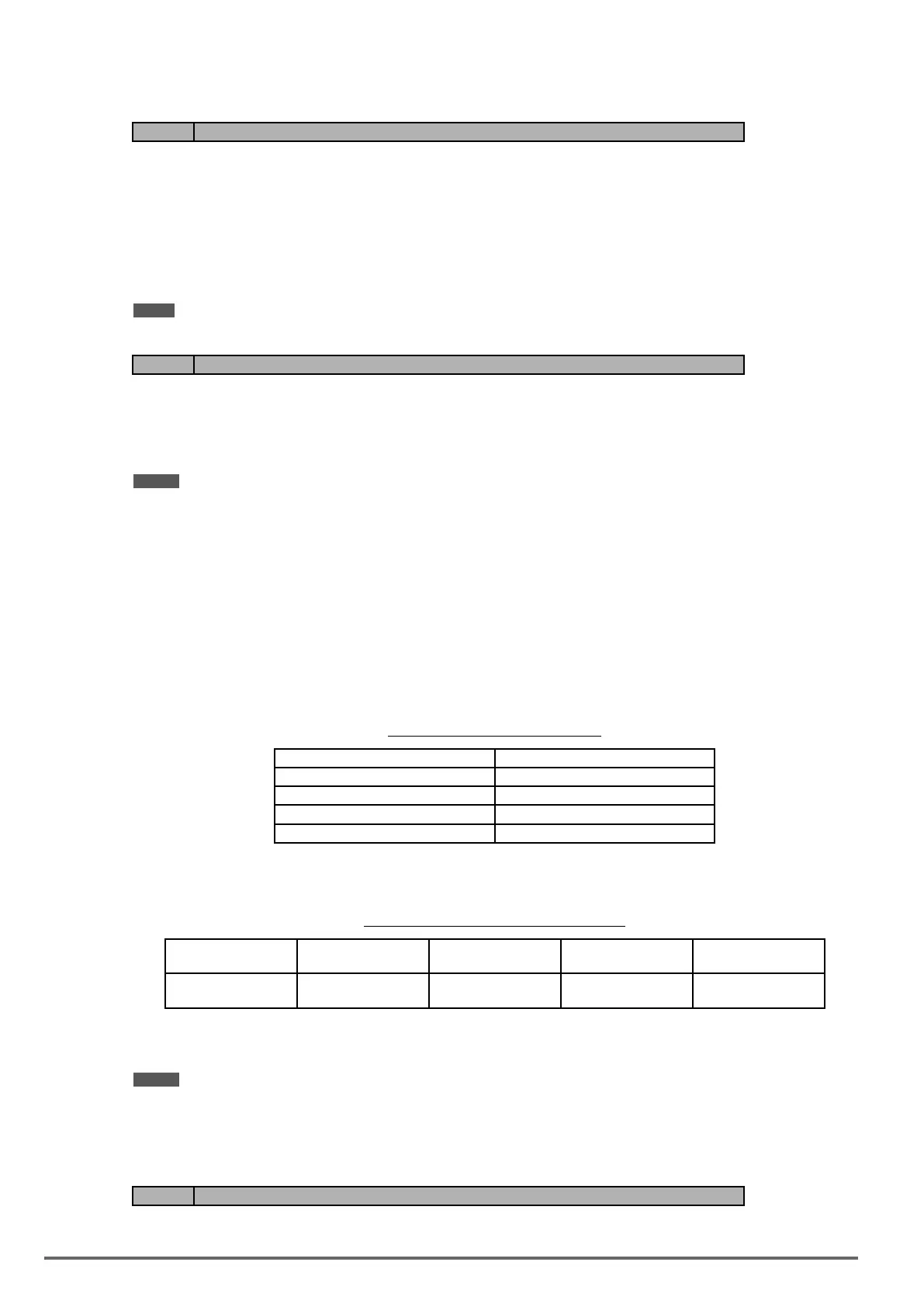
Refer to the carrier frequency Table 4.4.14.
Table4.4.14Carrierfrequencysettings
Carrier frequency (11-01=2 to 16)) 2KHz--6K--10K--16kHz
Motor noise High -------------------- Low
Output current waveform Fair --------------------- Better
Noise interference Low---------------------high
Leakage current Low---------------------high
If cable length between the inverter and the motor is too long, the high-frequency leakage current will cause an
increase in inverter output current, which might affect peripheral devices. Adjust the carrier frequency to avoid
this as shown in table 4.4.15.
Table4.4.15Cablelengthandcarrierfrequency
Wire length < 30 Meter (98ft) up to 50 Meter
(164 ft)
up to 100 Meter
(328ft)
> 100 Meter*
> 328ft
Carrier frequency
(11-01 value )
Max. value 16kHz
(11-01=16kHz)
Max. value 10KHz
(11-01=10KHz)
Maxi. value 5KHz
(11-01=5KHz)
Max. value 2KHz
(11-01=2KHz)
*. If Cable is longer than 200m, the output dv/dt lter or output reactor is required.
Notes:
(1) Reduce the carrier frequency if the torque does not match the speed.
(2) In V/f and V/f + PG control modes, the carrier frequency is determined by parameters 11-30 (Carrier fre-
quency max. limit), 11-31 (Carrier frequency lower limit) and 11-32 (Carrier frequency proportional gain).
Code Parameter Name / Range
11-02 Soft PWM Function Selection
224 VDI100 • Instruction manual

 Loading...


