LED display Description Possible causes Corrective action
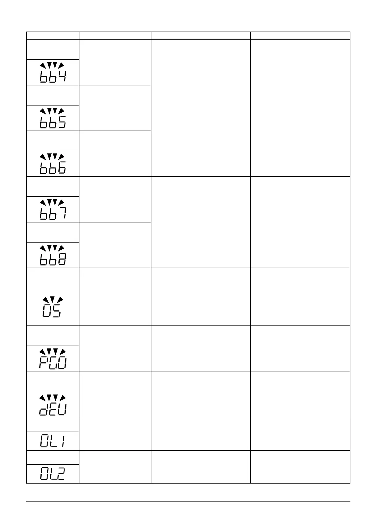
bb4
(flash)
External baseblock
External base block
(Terminal S4)
•Multifunction digital input external baseblock
active
•Multi-function input function set incorrectly.
•Check wiring
bb5
(flash)
External baseblock
External base block
(Terminal S5)
bb6
(flash)
External baseblock
External base block
(Terminal S6)
bb7
(flash)
External baseblock
External base block
(Terminal S7)
•Multifunction digital input external baseblock
active
•Multi-function input function set incorrectly.
•Check wiring
bb8
(flash)
External baseblock
External base block
(Terminal S8)
OS
(flash)
Motor over speed
Motor speed exceeds level set
in 20-20 (PG Over speed Level)
for the time set in 20-21 (PG over
speed time). Active when 20-19
(= 0 or 1).
This fault is active V/f + PG and
SV control mode (00-00 = 1
or 3 or 4). Motor speed can be
monitored by 12-22
•Motor speed overshoot (ASR)
•PG ppr set incorrectly.
•Overspeed parameters set incorrectly.
•Check ASR parameters group 21.
•Check PG parameters
•Check overspeed parameters 20-20/20-12.
PGO
(flash)
PG open circuit
PG pulses are not received by the
inverter for the time specified in
20-26 (PG open circuit detection
time).
This fault is active V/f + PG and
SV control mode (00-00 = 1 or
3 or 4).
•PG cable disconnected.
•PG has no power.
•Mechanical brake active preventing motor
from turning.
•Check PG wiring.
•Check PG power-supply.
•Make sure brake is released.
DEV
(flash)
Speed deviation
Motor speed rises above 20-23
level (PG speed deviation level)
for the time specified in 20-24 (PG
deviation time).Active when pa-
rameter 20-22(=0 or 1). This fault
is active V/f + PG and SV control
mode (00-00 = 1 or 3 or 4).
•Load too heavy
•Mechanical brake active preventing motor
from turning.
•PG wiring error.
•PG parameters (group 20) set incorrectly.
•Acceleration / deceleration time set to short.
•Check load
•Make sure brake is released.
•Check PG wiring.
•Check PG parameters 20-23/20-24.
•Increase Acceleration / deceleration time.
OL1
Motor overload
Internal motor overload protection
tripped, active when protection
curve 08-05 = xxx1.
•Voltage setting V/f mode too high, resulting in
over-excitation of the motor.
•Motor rated current (02-01) set incorrectly.
•Load too heavy
•Check V/f curve.
•Check motor rated current
•Check and reduce motor load, check and
operation duty cycle.
OL2
Inverter overload
Inverter thermal overload protec-
tion tripped. If an inverter overload
occurs 4 times in five minutes,
it is required to wait 4 minutes
before resetting the fault.
•Voltage setting V/f mode too high, resulting in
over-excitation of the motor.
•Inverter rating too small.
•Load too heavy.
•Check V/f curve.
•Replace inverter with larger rating.
•Check and reduce motor load, check and
operation duty cycle.
VDI100 • Instruction manual 335

 Loading...


