5. Check Motor Rotation and Direction
This test is to be performed solely from the inverter keypad. Apply power to the inverter after all the electrical
connections have been made and protective covers have been re-attached.
Motor rotation and direction only applies to standard AC motors with a base frequency of 60Hz. For 50Hz or other
frequency AC motors please set the max frequency and base frequency in group 01 accordingly before running the
motors.
Larotationetladirectiondumoteurs’appliquentuniquementauxmoteursCAstandardavecunefréquencede
basede60Hz.PourlesmoteursCAavecunefréquencede50Hzouautre,réglerenconséquencelesfré-
quencesmaximumetdebasedanslegroupe01avantdeprocéderàleurdémarrage.
• LED Keypad Display (KB-LED-VDI100)
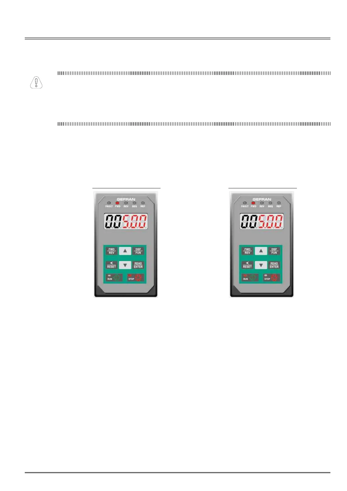
At this point, DONOTRUNTHEMOTOR, the LED keypad should display as shown below in Fig. 5.1 and all
LEDs are ashing. Next press the RUN key, all LEDs light on. See Fig 5.2. The motor should now be oper-
ating at low speed running in forward (clockwise) direction. The value shown in the screen will change from
000.00Hz to 005.00Hz. Next press STOP key to stop the motor.
Fig5.1:LEDKeypad(Stopped) Fig5.2:LEDKeypad(Running)
• LCD Keypad Display (KB-LCD-VDI100)
At this point, DONOTRUNTHEMOTOR, the LCD keypad should display as shown below in Fig. 5.3 and the
speed reference 12-16=005.00Hz should be blinking at the parameter code “12-16”. Next press the RUN key,
see Fig 5.4. The motor should now be operating at low speed running in forward (clockwise) direction. The
parameter code 12-17 shown at the bottom left corner of the screen will change from 12-17=000.00Hz to 12-
17=005.00Hz. Next press STOP key to stop the motor.
VDI100 • Instruction manual 309

 Loading...


