3.12. Inverter Wiring
Wiring Precautions
• Do NOT remove any protective covers or attempt any wiring while input power is applied. Connect all
wiring before applying input power. When making wiring changes after power up, remove input power
and wait a minimum of ve minutes after power has been turned off before starting. Also conrm that the
charge lamp is off and that DC voltage between terminals B1/P or (+) and (-) does not exceed 25V, other-
wise electric shock may result.
• Only authorized personnel should work on the equipment. (Take off metal jewelry such as watches and
rings and use insulated tools.), otherwise electric shock or injury may result.
Précautions relatives aux câblages
• NEPASretirerlescachesdeprotectionnitenterderéaliserdescâblagessoustension.Branchertousles
câblagesavantd’alimenterl’équipement.Encasdemodicationsdescâblagesaprèslamisesousten-
sion,couperl’alimentationetattendreaumoinscinqminutesavantd’intervenir.Vérieraussiqueletémoin
dechargeestéteintetquelatensionCCentrelesterminauxB1/Pou(+)et(-)nedépassepas25V.Le
non-respectdecetteprescriptionpeutentraînerdesrisquesd’électrocution.
• Seulunpersonnelautorisépeutintervenirsurl’équipement.Eviterdeporterdesbijoux(montres,bagues,
etc.)etutiliserdesoutilsisolés.Lenon-respectdecetteprescriptionpeutentraînerdesrisquesd’électroc-
utionetdeblessures.
(A)Powerinputterminals
1. The Input power supply voltage can be connected in any phase sequence to power input terminals R/L1, S/
L2, or T/L3 on the terminal block.
2. DO NOT connect the AC input power source to the output terminals U/T1, V/T2 and. W/T3.
3. Connect the output terminals U/T1, V/T2, W/T3 to motor lead wires U/T1, V/T2, and W/T3, respectively.
4. Check that the motor rotates forward with the forward run source. If it does not, swap any 2 of the output
cables to change motor direction.
5. DO NOT connect phase correcting capacitors or LC/RC noise lter to the output circuit.
(B)Grounding
1. Connect the ground terminal (E) to ground having a resistance of less than 100Ω.
2. Do not share the ground wire with other devices, such as welding machines or power tools.
3. Always use a ground wire that complies with the local codes and standards for electrical equipment and
minimize the length of ground wire.
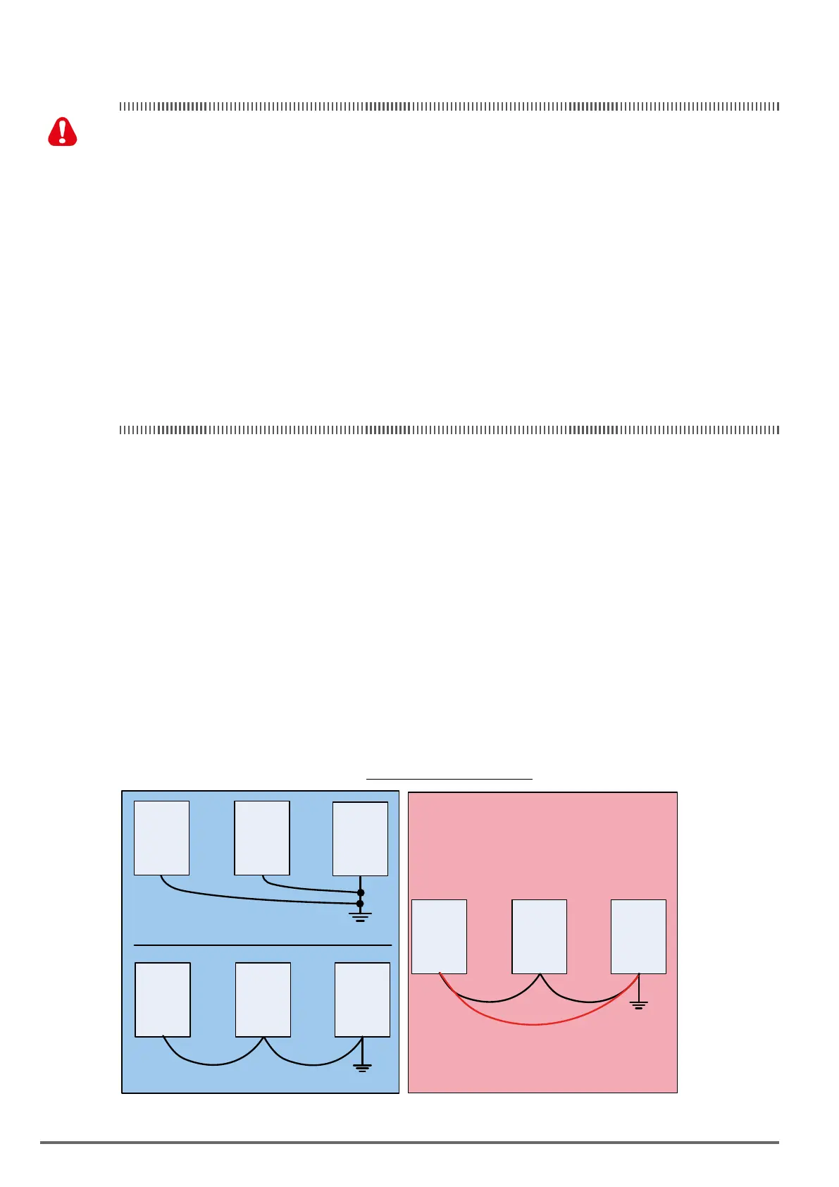
4. When using more than one inverter, be careful not to loop the ground wire, as shown below in Fig. 3.12.1.
Figure3.12.1:InverterGrounding
a) Correct
b) Correct
c) Incorrect
Loop
VDI100 VDI100 VDI100
VDI100 VDI100 VDI100
VDI100 VDI100 VDI100
30 VDI100 • Instruction manual

 Loading...


