4.6. Modbus Protocol Descriptions
4.6.1. Communication Connection and Data Frame
The inverter can communicate with a PC or PLC via RS485 or RS232 using the Modbus RTU or Modbus ASCII
protocol. The maximum frame length is 80 bytes.
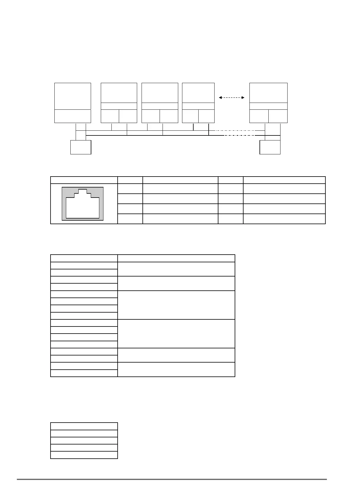
Network Connection
Controller
(PLC / HMI or
PC)
VDI100
Node
Address 01
VDI100
Node
Address 02
VDI100
Node
Address 03
VDI100
Node
Address FE
6NC 6NC 6NC 6NC
RS-485
Interface
S(+) S(-) S(+) S(-) S(+) S(-) S(+) S(-)
120Ω
1/4w
120Ω
1/4w
** Terminate the communications line with a (120 ohm, 1/4 watt) resistor at both ends.
CN6 Pin out PIN Signal PIN Signal
876 5 4321
1 RS-485 S+ signal 5 Tx signal
2 RS-485 S- signal 6 RS-485 S- signal
3 RS-485 S+ signal 7 VDC of isolated 5V power supply
4 Rx signal 8 GND of isolated 5V power supply
For RS-485 communication use pin 1 or pin 3 for S (+) and pin 2 or pin 6 for S (-)
Data Format Frame
STX(3AH) Start Bit = 3AH
Node Address Hi
Communication Address (Station):
2-digit ASCII Code
Node Address Lo
Function Hi
Function Code (command):
2-digit ASCII Code
Function Lo
Command Start Address
Command Start byte:
4-digit ASCII Code
Command Start Address
Command Start Address
Command Start Address
Data length
The length of the command:
4-digit ASCII Code
Data length
Data length
Data length
LRC Check Hi
LRC Check Code:
2-digit ASCII Code
LRC Check Lo
END Hi
End Byte:
END Hi=CR(0DH), END Li = LF(0AH)
END Lo
Data Frame for RTU Mode
Master (PLC etc.) sends request to follower (inverter), and the follower sends a response to the master (PC,
PLC). The data received is illustrated here.
The data length varies depending on the command (Function).
Node Address
Function Code
DATA
CRC CHECK
Signal Interval
** The inverter response time is 10ms.
294 VDI100 • Instruction manual

 Loading...


