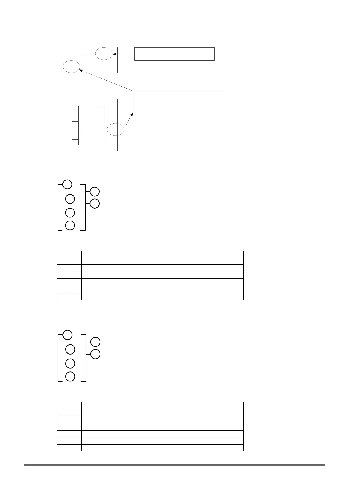
Example:
(F1)
F1
I1
(Q1)
RUN/STOP of F1 is determined by
ON/OFF of I1
10.00
10.00
60.0
30.0
F1
M1
M2
F1 is ON inverter starts running
and at the same time, the F1 input of the
ladder program is ON as well.
Input from Function Program
Input from the Ladder Program
n
n
5: Summation and subtraction functions
5
6
2
1
3
4
RESULT (calculation result) = V1+ V2- V3
Symbol Description
Calculation result : RESULT
Addend V1(AS1~AS4,MD1~MD4,T1~T8,C1~C8,V1~V7, constant )
Addend V2(AS1~AS4,MD1~MD4,T1~T8,C1~C8,V1~V7, constant )
Subtrahend V3(AS1~AS4,MD1~MD4,T1~T8,C1~C8,V1~V7, constant )
Coil output of error signal (M1~MF)
Addition and subtraction modes number (AS1~AS4)
6: Multiplication and division modes
5
6
2
1
3
4
RESULT (calculation result) =V1*V2/V3
Symbol Description
Calculation result : RESULT
Multiplier V1(AS1~AS4,MD1~MD4,T1~T8,C1~C8,V1~V7, constant )
Multiplier V2(AS1~AS4,MD1~MD4,T1~T8,C1~C8,V1~V7, constant )
Divisor V3(AS1~AS4,MD1~MD4,T1~T8,C1~C8,V1~V7, constant )
Coil output of error signal (M1~MF)
Multiplication and division modes number (MD1~ MD4)
VDI100 • Instruction manual 293

 Loading...


