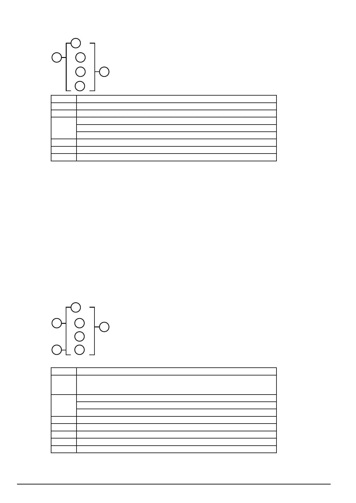
3: Analog comparator function
1
3
4
2
6
5
Symbol Description
Analog comparator mode (1~3)
Input comparison value selection (AS1~AS4,MD1~MD4,T1~T8,C1~C8,V1~V7)
Current analog input value
Set the reference comparison value (Upper limit)
(AS1~AS4,MD1~MD4,T1~T8,C1~C8,V1~V7, constant )
Set the reference comparison value (lower limit)
(AS1~AS4,MD1~MD4,T1~T8,C1~C8,V1~V7, constant )
Comparator output (G1 to G8, there are a total of 8 comparators)
The description of analog comparison mode:
(1) Analog comparison mode 1 ( ≤ , ON)
(2) Analog comparison mode 2 ( ≥ , ON)
(3) Analog comparison mode 3 ( ≤ ≤ , ON)
Inputcomparisonvalueselection(V1~V7)
(1) Input comparison value selection = V1: Set frequency
(2) Input comparison value selection = V2: Operation frequency
(3) Input comparison value selection = V3: AI1 input value
(4) Input comparison value selection = V4: AI2 input value
(5) Input comparison value selection = V5: Keypad input value
(6) Input comparison value selection = V6: Operation current
(7) Input comparison value selection = V7: Torque value
4: Operation control function
5
6
7
2
1
3
4
Symbol Description
Forward /Reversal control can be set by ( I1~f8 )
OFF: Forward (FWD)
ON: Reversal (REV)
Speed terminal control can be set by ( I1~f8 )
OFF: Operation based on set frequency
ON: Operation based on frequency of speed
Set frequency (can be constant or V3,V4,V5 )
Speed frequency (can be constant or V3,V4,V5)
Acceleration time (ACC Time)
Deceleration time (DEC Time)
Operation command output (F1 to F8, there are a total of 8 operation control functions)
292 VDI100 • Instruction manual

 Loading...


