0: Disable
1: Enable
11-02=0:
Soft PWM control disabled.
11-02=1:
Soft PWM control enabled. Soft PWM control can improve the ‘metal’ noise produced by the motor,
more comfortable for the human ear. At the same time, Soft PWM also limits RFI noise to a minimum level.
The default setting of Soft PWM control is disabled. Soft PWM cannot be set if carrier frequency set in 11-01 is
higher than 8 kHz.
Code Parameter Name / Range
11-03 Automatic carrier lowering selection
0: Disable
1: Enable
11-03=0: Automatic carrier frequency reduction during an overheat condition is disabled.
11-03=1: Carrier frequency is automatically lowered in case the inverter heatsink overheated and will return
to carrier frequency set in parameter 11-01 when the inverter temperature returns to normal. See section 3 for
more information.
Code Parameter Name / Range
11-04 S curve time setting at the start of acceleration
11-05 S curve time setting at the end of acceleration
11-06 S curve time setting at the start of deceleration
11-07 S curve time setting at the end of deceleration
0.00~2.50 s
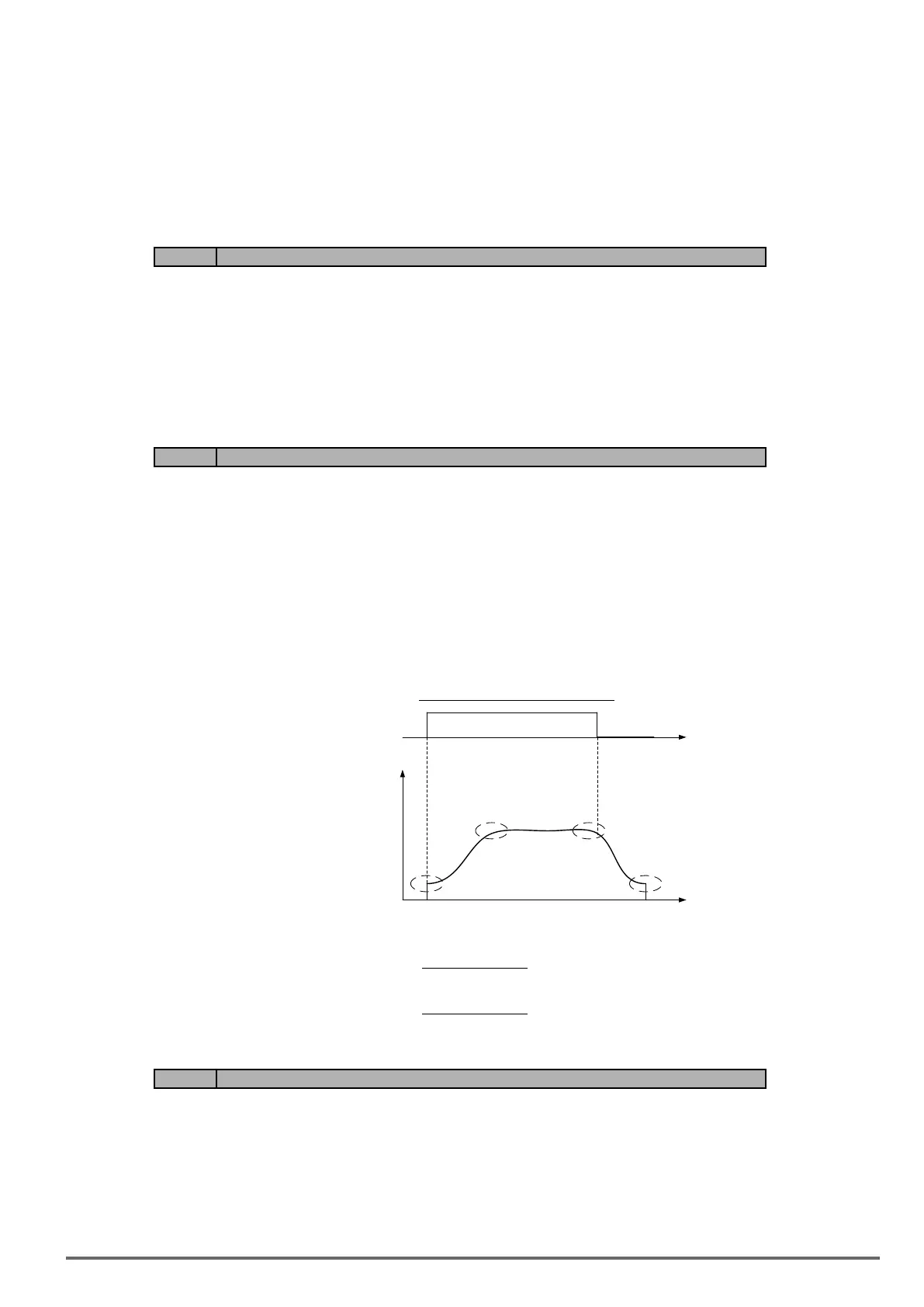
The S curve function for acceleration / deceleration is used to reduce mechanical impact caused by the load
during momentary starting and stopping of the inverter. To use the S curve function set the time for acceleration
start point (11-04), acceleration end point (11-05), deceleration start point (11-06) and deceleration end point
(11-07). Refer to gure 4.4.85 for more information.
Figure4.4.85Scurvecharacteristic
S1
S2
S3
S4
ON
OFF
11-04
11-05 11-06
11-07
t
Output
Frequency
Run
Command
t
Total acceleration and deceleration time when the S curve is used:
Accelerating time = Accelerating time 1 (or 2) +
(11-04) + (11-05)
2
Deceleration time = Deceleration time 1 (or 2) +
(11-06) + (11-07)
2
Code Parameter Name / Range
11-08 Jump frequency 1
11-09 Jump frequency 2
11-10 Jump frequency 3
0.0~599.0 Hz
11-11 Jump frequency width
0.0~25.5 Hz
VDI100 • Instruction manual
225

 Loading...


