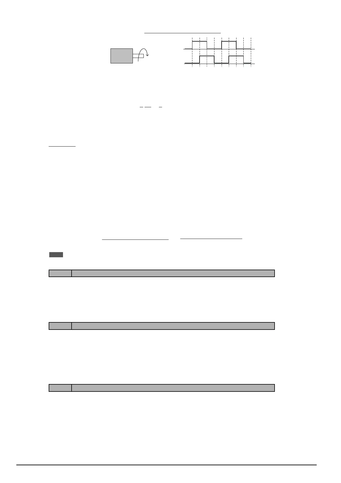
Figure4.4.120PGoperationdirection
phase A
phase B
PG
CW
(6) PG pulse dividing ratio (20-29)
Sets the pulse divider ratio between the PG input and PG output.
The left most digit (3rd) represent the numerator and the last to represent the denominator.
Ratio is calculated as follows: 20-29= □ □□, = n kk
Range n: 0 to 1
Range k: 1 to 32
Ratio = (1+n)/k
Examples:
20-29=001 → n=0, k=1, proportion = (1+0)/1=1
20-29=032 → n=0, k=32, proportion = (1+0)/32=1/32
20-29=132 → n=1, k=32, proportion = (1+1)/32=1/16
(7) Gear ratio of PG and motor (20-30, 20-31).
Gear ratio species when a gearbox is connected between the PG and the motor
a) Set the gear ratio of the load side parameter 20-31.
b) Set the gear ratio of the motor side parameter 20-30.
Motor speed is calculated as follows:
Motor Speed(RPM) =
No. of input pulses from PG × 60
PG pulses (20-27)
No. of PG gear teeth 2 (20-31)
No. of PG gear teeth 1 (20-30)
×
Note: The response speed in V / F + PG mode is less than that of SV mode.
Code Parameter Name / Range
20-32 Special encoder selection
0: None
1: Resolver
Select encoder type. Power to the inverter needs to be cycled for changes to take effect.
Code Parameter Name / Range
20-34 Compensation Gain of Derating
0~25600
This gain effect is the same as ASR proportional gain (20-00, 20-02). And if this parameter is coupled with low-
pass lter time constant (20-35), it can avoid oscillation.
It is suggested that the setting value of parameter 20-34 is 30~50.
Code Parameter Name / Range
20-35 Compensation Time of Derating
0~30000 mSec
This time constant is used for suppressing the oscillation produced by 20-34. But too large compensation time
constant will cause slower output response and then is unfavorable for turned compensation.
It is suggested that the setting value of parameter 20-35 is 50~100ms.
Refer to Fig.4.4.108 and Fig. 4.4.109. Torque compensation function of derating can reduce the characteristics
of ASR turning around under shock load.
270 VDI100 • Instruction manual

 Loading...


