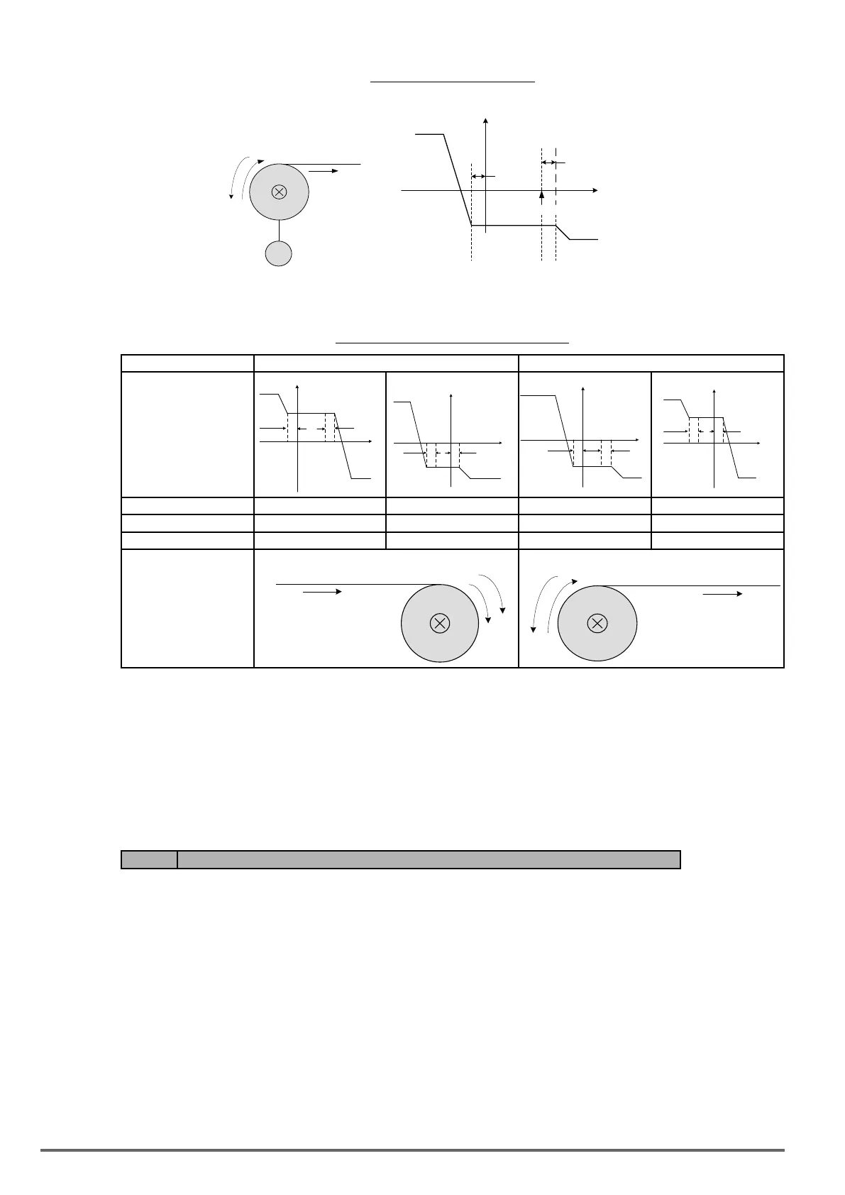
Figure4.4.125Unwindoperation
Torque Limit
(21-08)
(T)
Tref
motor speed
(N)
Torque Limit
(21-07)
21-04
21-04
Speed Limit Setting
N
T
M
Line direction
The relationship among Tref (torque reference), NLmt (speed limit) and N (motor speed) is shown below when
used in winding operation and roll-out operation.
Figure4.4.126Windingandroll-outoperations
Operations Winding operation Unwind operation
T-N curve
21-07
21-04
21-04
T
T
ref
N
Lmt
N
21-08
21-08
21-07
21-04
21-04
T
T
ref
N
Lmt
N
21-08
21-04
T
T
ref
N
Lmt
N
21-04
21-08
21-07
21-04
21-04
T
T
ref
N
Lmt
N
Operation direction Forward Reverse Forward Reverse
Tref ( Torque reference) + − − +
NLmt ( Speed limit ) + − + −
Architecture
N
T
Line direction
N
T
Line direction
Torque compensation
Torque compensation is used to compensate for torque loss due to mechanical damage or other losses. Mul-
ti-function analog input AI2 can used for torque compensation (04-05 = 16, 04-07/08 Gain/ Bias).
Set the appropriate signal level for the torque compensation. The torque compensation direction is based on
the analog signal polarity, not by the direction of the run command.
When Tcomp is xed at a positive voltage (or current) results in a positive torque compensation (the rotation of
motor shaft is counterclockwise).
Code Parameter Name / Range
21-05 Positive torque limit
0~300 %
21-06 Negative torque limit
0~300 %
21-07 Forward regenerating torque limit
0~300 %
21-08 Reversal regenerating torque limit
0~300 %
Use the torque limit function to limit the torque applied to the load, or limit the regenerative torque.
In speed control the torque limit function has a higher priority than the motor speed control and compensation.
This might result in extended acceleration, deceleration times and a reduction in motor speed.
274 VDI100 • Instruction manual

 Loading...


