EasyManuals Logo

Gema OptiMove CR09-C User Manual

Gema OptiMove CR09-C
78 pages
To Next Page IconTo Next Page
To Previous Page IconTo Previous Page
Page #35 background imageLoading...
Page #35 background image
Rev. 00 12/22
OptiMove CR09-C Start-up 35
Hardware
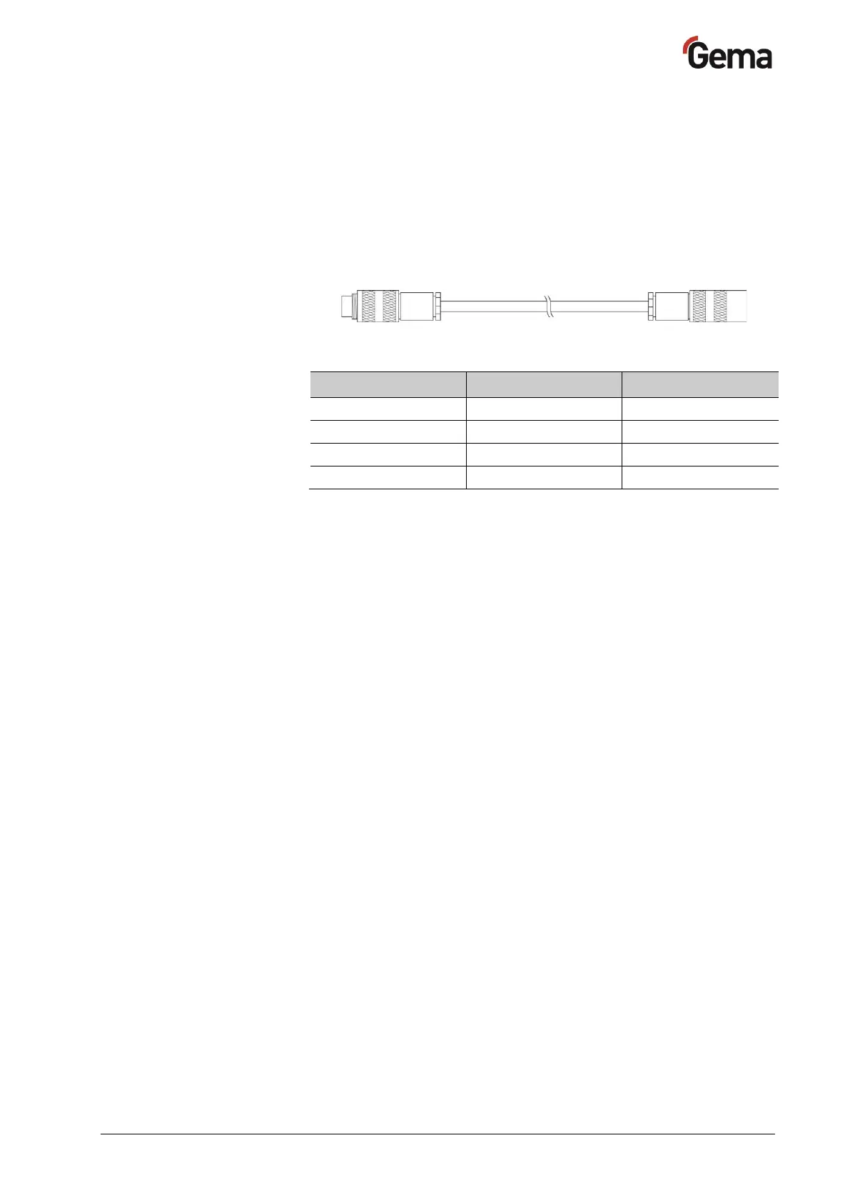
The control units are connected to the central PLC control unit via 4 pin
CAN bus cables. The last bus client is fitted with a terminal plug with
terminal resistor in order to terminate the network correctly. A maximum
of up to 127 Control units can be operated in a network.
CAN bus cable plug assignment
Fig. 10: CAN bus cable
Pin
Signal
Color
1
GND
white
2
+24 VDC
black
3
CAN H
black
4
CAN L
black

Table of Contents

Questions and Answers:

Question and Answer IconNeed help?

Do you have a question about the Gema OptiMove CR09-C and is the answer not in the manual?

Gema OptiMove CR09-C Specifications

General IconGeneral
BrandGema
ModelOptiMove CR09-C
CategoryIndustrial Equipment
LanguageEnglish

Related product manuals