EasyManuals Logo

Gema OptiMove CR09-C User Manual

Gema OptiMove CR09-C
78 pages
To Next Page IconTo Next Page
To Previous Page IconTo Previous Page
Page #41 background imageLoading...
Page #41 background image
Rev. 00 12/22
OptiMove CR09-C Start-up 41
Software description
For each OptiMove axis control unit, one strobe signal and one error
signal exists. The data signals and the identification number signals are
used in common for all OptiMove control units. The OptiMove control unit
takes over the data with the negative edge of the strobe signal.
Explanation:
The simultaneous transmission of identical data to all OptiMove units only
occurs on the negative edge of all strobe signals.
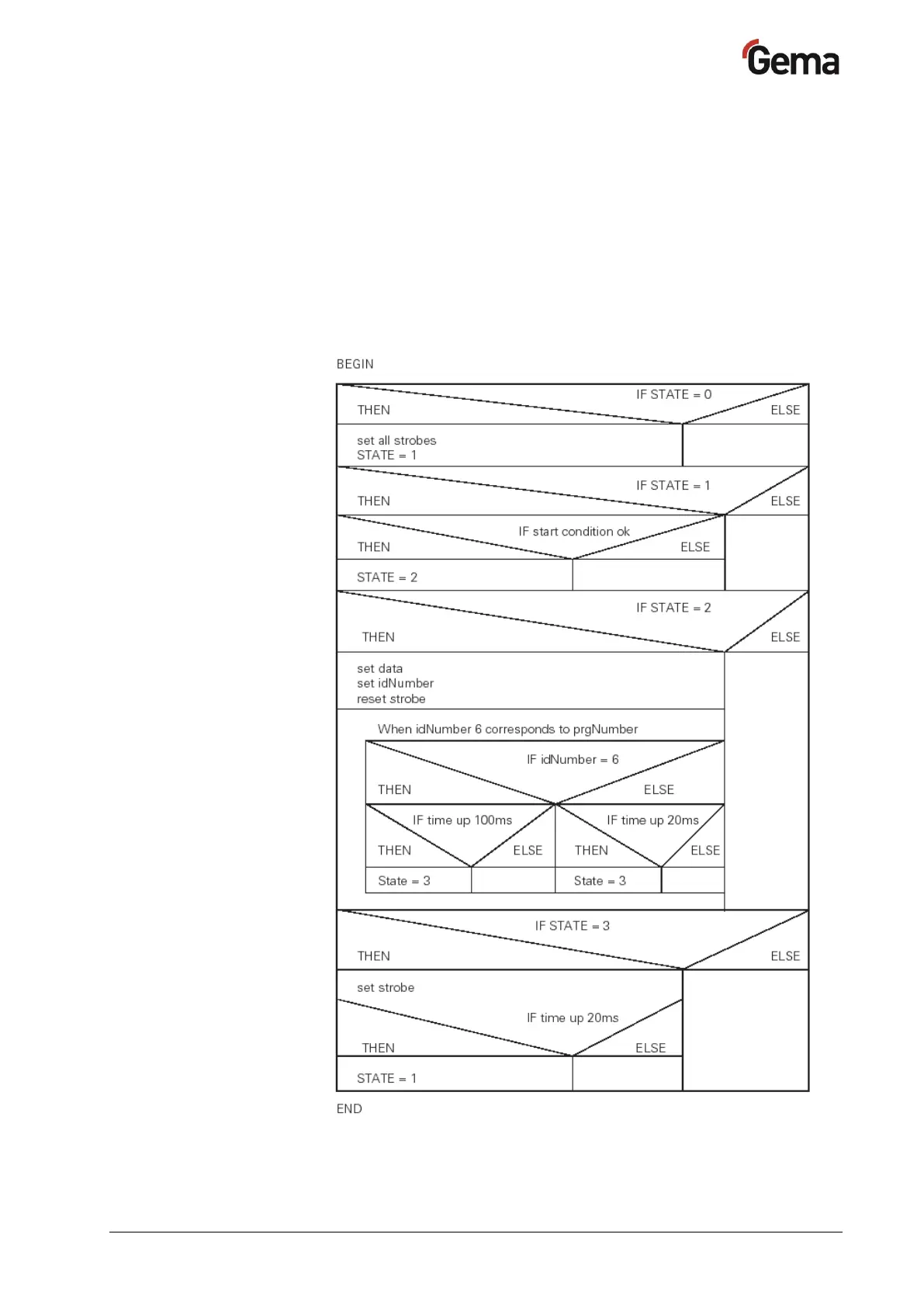
Example of a PLC program:
Program procedure diagram

Table of Contents

Questions and Answers:

Question and Answer IconNeed help?

Do you have a question about the Gema OptiMove CR09-C and is the answer not in the manual?

Gema OptiMove CR09-C Specifications

General IconGeneral
BrandGema
ModelOptiMove CR09-C
CategoryIndustrial Equipment
LanguageEnglish

Related product manuals