PART 4
ENGINE/DC CONTROL
Page 126
Section 4.5
Diagnostic Tests
2. Disconnect the choke solenoid.
3. Set a Volt-Ohm-Milliammeter (VOM) to measure DC
voltage.
4. Refer to Figure 132. Connect the positive meter test lead
to Pin 1 (Wire 14) of the female side of the CS connector
going to the control panel and connect the negative meter
test lead to Pin 2 (Wire 90).
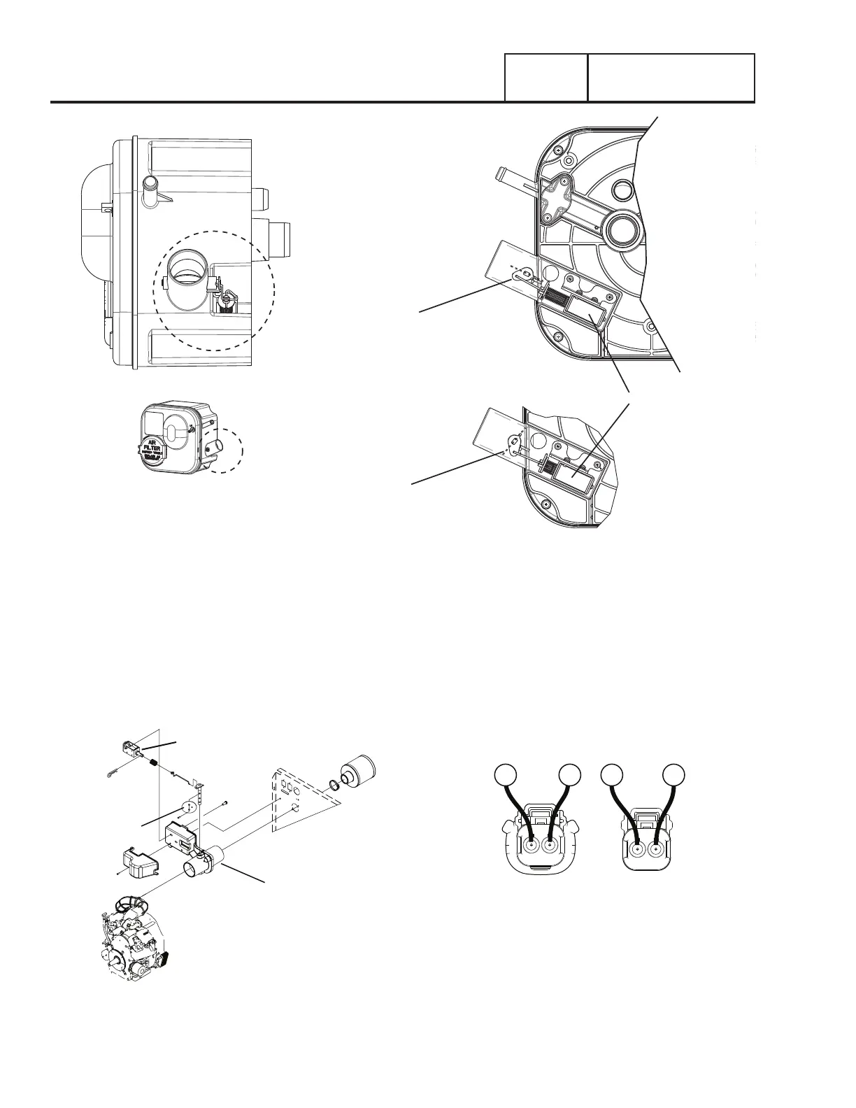
CHOKE PLATE
CHOKE SOLENOID
CHOKE HOUSING
Figure 131. Exploded View Showing Location of Choke Plate -
10kW Units
5. Set the AUTO-OFF-MANUAL switch to MANUAL. While
cranking, the VOM should indicate battery voltage
cyclically.
a. If the VOM did NOT indicate battery voltage, verify
CONTINUITY of Wire 90 between the connector Pin
1 J4 (Wire 90) and verify CONTINUITY of Wire 14
between the connector Pin 9 J4 (Wire 14). Repair or
replace any wiring as needed.
b. If the VOM indicated a cyclical battery voltage proceed
to Step 6.
FEMALE SIDE
MALE SIDE
2 1
1 2
90
9014
14
Figure 132. C3 Choke Solenoid Connector
6. Set a VOM to measure resistance.
7. Connect one meter test lead to Pin 1(Wire 14) on the male
side of the CS connector and the other meter test lead to
Pin 2 (Wire 90), measure and record the resistance.
8. Reconnect the choke solenoid.
Figure 130. 8kW Choke Solenoid
CHOKE VALVE IN OPEN POSITION
AIR BOX
CHOKE SOLENOID
CHOKE VALVE IN CLOSED POSITION

 Loading...


