PART 4
ENGINE/DC CONTROL
Page 132
Section 4.5
Diagnostic Tests
was disconnected in Step 7d. The engine should crank
once the jumper from 194 is connected.
8. If spark was not indicated, replace magnetos.
Note: If gap is only adjusted, ensure to properly test the
magnetos by cranking the engine over before reassem-
bly occurs. Spark should be present on both cylinders
before reassembly should be completed.
9. If air gap was not out of adjustment, test ground wires.
10. Set a VOM to the measure resistance.
11. Disconnect the engine wire harness from the ignition
magnetos (Figure 143).
a. On V-twin generators, remove Wire 18 from the stud
located above the oil cooler. See Figure 140.
b. On single cylinder generators, disconnect Wire 18 at
the bullet connector. See Figure 141.
SPARK PLUG
SPARK PLUG
WIRE 18 TO
CIRCUIT BOARD
STUD CONNECTOR
ENGINE
WIRE
HARNESS
REMOVE LEADS
Figure 143. Engine Ground Harness
12. Connect one meter test lead to one of the wires removed
from the ignition magneto(s). Connect the other test lead to
frame ground. INFINITY should be measured. If CONTINUITY
is measured, replace the shutdown harness.
13. Now check the flywheel magnet by holding a screwdriver
at the extreme end of its handle and with its point down.
When the tip of the screwdriver is moved to within 3/4
inch (19mm) of the magnet, the blade should be pulled in
against the magnet.
14. For rough running or hard starting engines check the flywheel
key. The flywheel's taper is locked on the crankshaft taper
by the torque of the flywheel nut. A keyway is provided for
alignment only and theoretically carries no load.
Note: If the flywheel key becomes sheared or even par-
tially sheared, ignition timing can change. Incorrect tim-
ing can result in hard starting or failure to start.
15. As stated earlier, the armature air gap is fixed for single
cylinder engine models and is not adjustable. Visually
inspect the armature air gap and hold down bolts.
Results
If sparking still does not occur after adjusting the armature
air gap, testing the ground wires and performing the basic
flywheel test, replace the ignition magneto(s).
Procedure, Replacing Magnetos:
1. Follow all steps of the Major Disassembly procedures that
are located in Section 6.
2. Once the magnetos are visible, make note to how they are
connected.
Note: Each magneto has its own part number. Verify the
part number prior to installation.
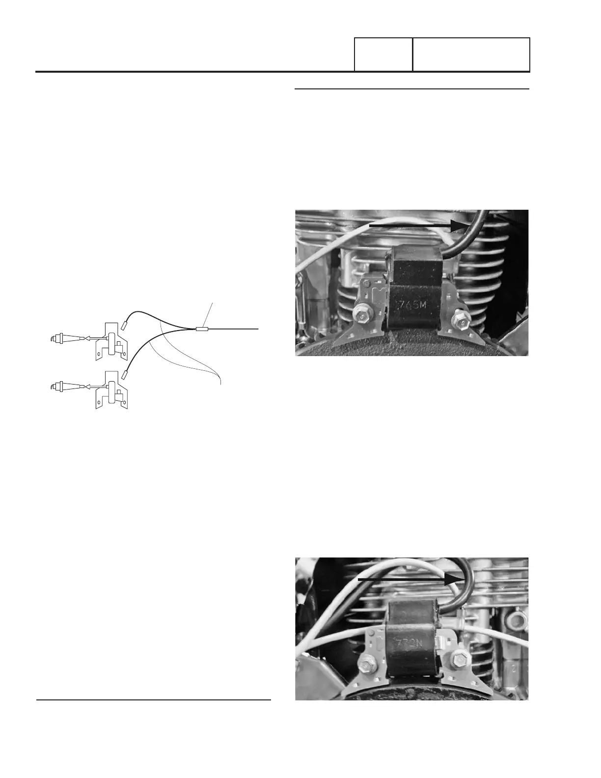
3. Cylinder one is the back cylinder (Figure 144) and cylinder
two is the front cylinder (Figure 145).
Figure 144. Cylinder One (Back, Short)
4. When installing new magnetos there will be one with a
short plug wire and one with a longer plug wire (Figure
146).
Note: Magneto gap to flywheel needs to be 0.010 inch.
5. Long plug wire (B) will be installed on front cylinder
(number two).
6. Short plug Wire (A) will be installed on back cylinder
(number one).
7. Verify installation of magnetos correctly by ensuring both
spark plug wires point to the back of the enclosure and
shutdown terminals are nearest cylinder head as shown in
Figures 147 and 148.
Figure 145. Cylinder Two (Front, Long)

 Loading...


