AutoVu SharpX mobile installation
tip.genetec.com | AutoVu Hardware Guide for SharpX Mobile Installation
EN.410.018-XS(6) | Last updated: October 6, 2016 38
6 Crimp ferrules (provided) to the camera wires.
Ensure that you use the appropriate ferrule for the wire gauge.
7 Twist the grey and yellow wires together until 1 cm (3/8 in.) from the connector.
TIP: For a cleaner installation, you can also twist the red, black and shield wires together.
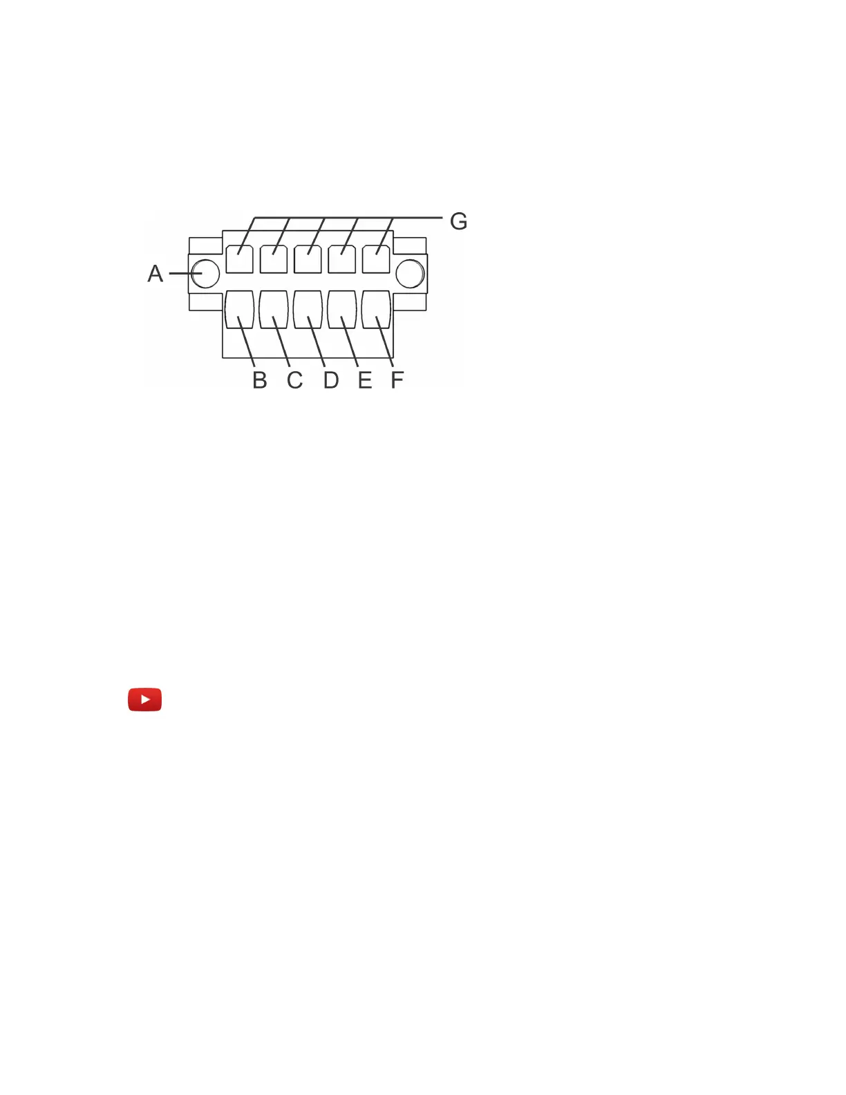
8 Insert the wires into the connector poles as indicated below.
• A: Securing screws
• B: Drain wire -tinned copper (S)
• C: Red wire (+)
• D: Black wire (-)
• E: Yellow wire (P)
• F: Grey wire (N)
• G: Tension clamps
Example
Watch this video to learn more. Click the Captions icon (CC) to turn on video captions in one of the
available languages.
After you finish
Repeat these steps for your other SharpX camera(s) as needed.
Related Topics
LED statuses on the SharpX camera unit on page 78
Securing wires using tension clamp connectors on page 31