Introduction
1
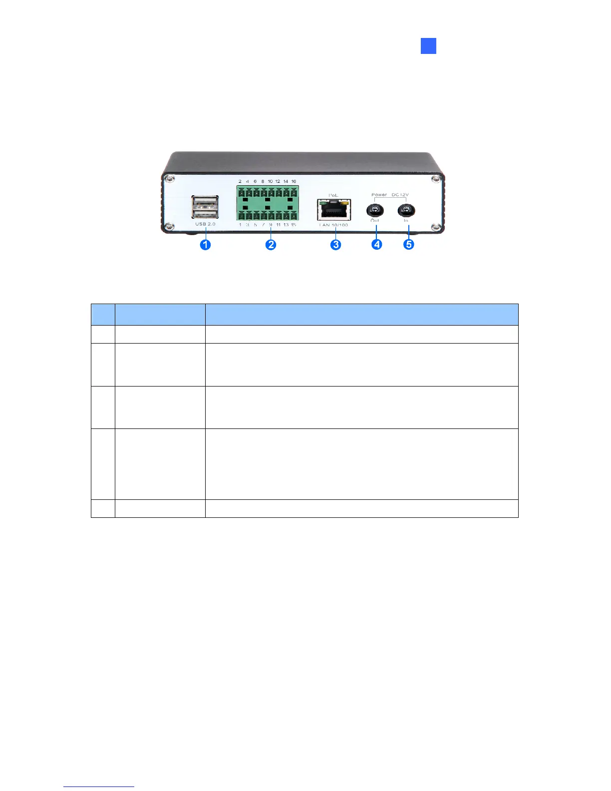
1.7.2 Rear View
1.7.2.2 GV-VS04H / GV-VS14
Figure 1-7
No. Name Function
1 USB Port 2 USB ports for installing portable storage devices.
2 Terminal Block
The connectors for digital input, relay output, PTZ camera,
Wiegand device and GPS module control. See Chapter 9 Auxiliary
Device Connectors.
3 Ethernet Port
A plug for a 10/100 Ethernet or PoE.
Note: GV-VS14 does not support PoE function.
4 Power Out
A plug to power on the camera, by using a DC Male-to-Male Cable,
directly through the GV-Video Server.
Note: When PoE is applied, you cannot power on the camera
through the GV-Video Server.
5 Power In A plug for power input.
9
 Loading...