MP-129 Installation
2–4
MP-129 INSTALLATION SEQUENCE
BURN HAZARD/SHOCK HAZARD: Turn OFF all electricity,
water, and steam to the sterilizer before starting the water-
saver installation. Touching live electrical connections and/or
exposure to live steam could cause serious injury.
Installation of the water-saver consists of:
1. Locating, mounting, and anchoring (page 2-5).
2. Installing the pressure switch (page 2-6).
3. Modifying the sterilizer piping (page 2-6).
4. Connecting the cold water supply (page 2-7).
5. Connecting the overflow drain (page 2-7).
6. Connecting the electrical cables:
a. MP-129 A & B (page 2-8).
b. MP-129 C & D (page 2-11).
7. Checking the rotation of the pump motor (page 2-14).
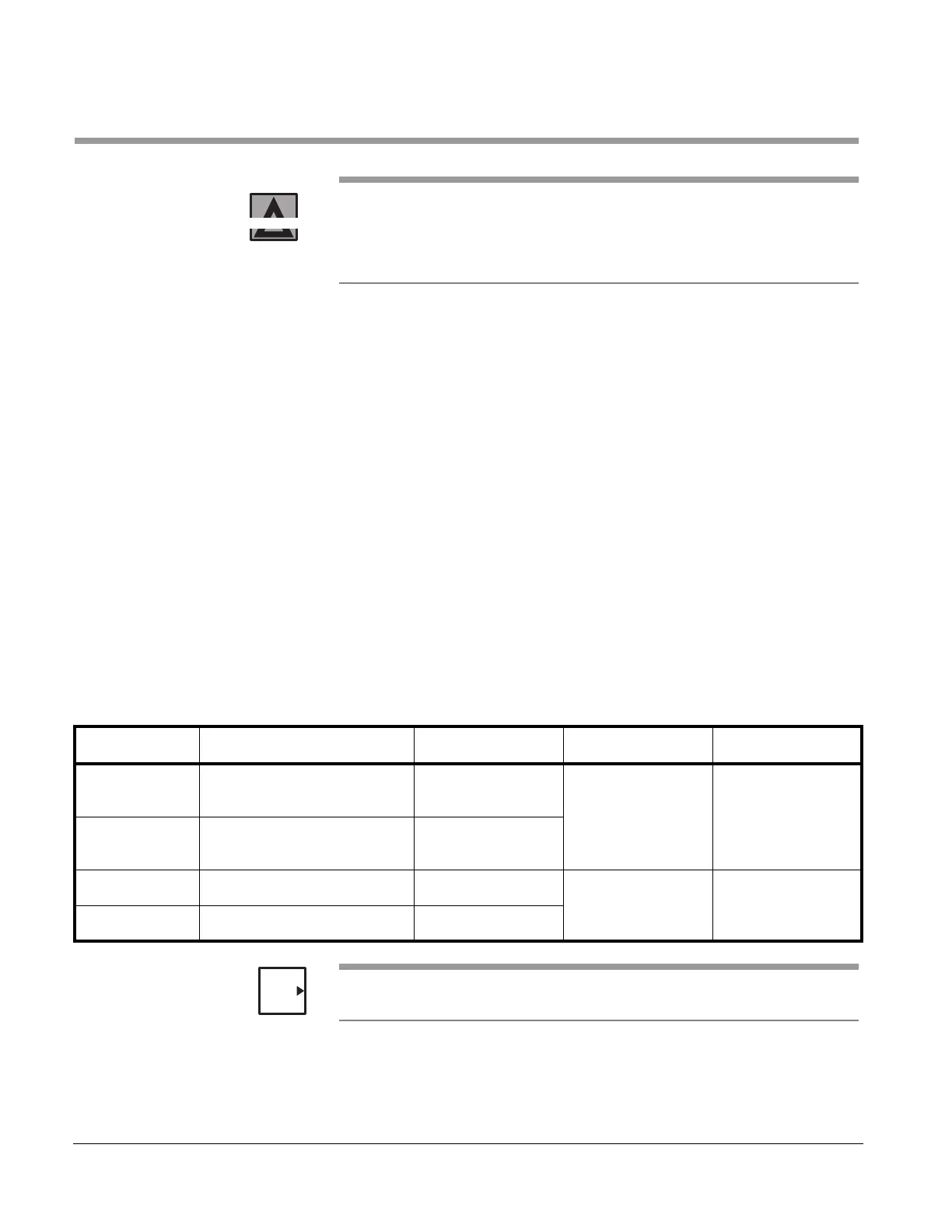
Refer to the engineering drawings listed in Table 2–1 during
installation of the MP-129 Water-Saver.
If an MP-129A is installed on a 400/500 Series sterilizer, refer to drawing
SK48835 for piping and wiring detail.
WARNING
Table 2–1. MP-129 Water-Saver Drawings
Water-Saver Sterilizer Model Piping Package Piping Schematic Wiring Diagram
MP-129A 100 Series
M/C 3500 Series
61301603246 P1925 W1297
MP-129B 200 Series
M/C 3600 Series
61301603247
MP-129C M/C 4233 (42") 531173 P1781 531181
MP-129D M/C 4233 (76") 531174
NOTE