MP-129 Installation
2–6
CONNECTING THE PIPING COMPONENTS
Each sterilizer being fitted with the water-saver must be modified by
installing pressure switch 1PS, solenoid valve 20SV, check valve 9CV, and
the copper tubing to connect into the water-saver.
Pressure Switch 1PS Pressure switch 1PS can be mounted in any convenient location, on or near
the sterilizer or water-saver, so that it can be piped into the chamber
pressure transducer line and wired to the sterilizer and water-saver.
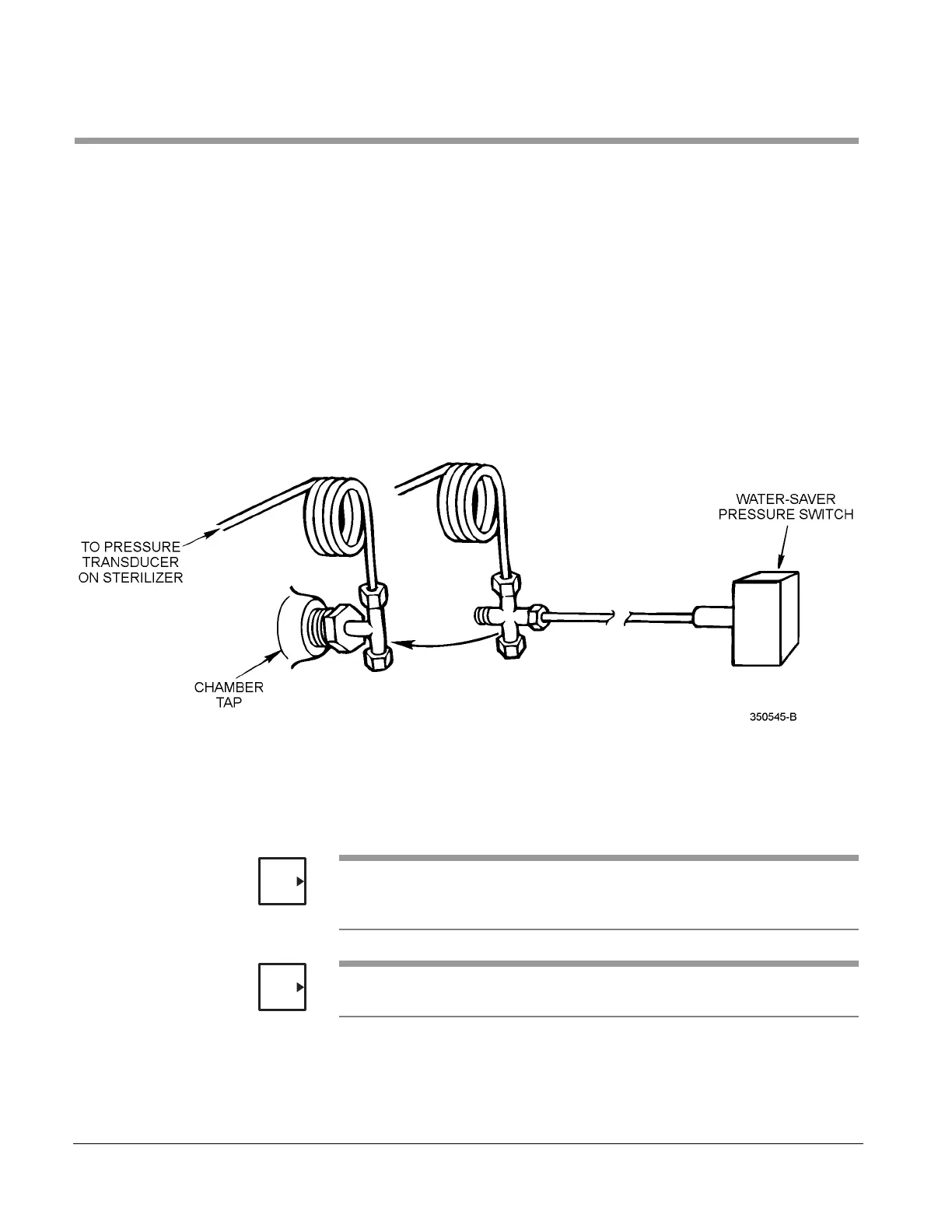
Connect a ¼" OD copper tubing (supplied by customer) from the pressure
switch to the chamber pressure line.
A convenient location is to tap into the ¼" OD coiled copper tubing from the
sterilizer pressure transducer.
Figure 2–1. PRESSURE SWITCH CONNECTION
Solenoid Valve 20SV and
Check Valve 9CV
Separate packages of fittings and components for the various sterilizer
models are listed in Table 2–1 on page 2-4. Refer to the piping assembly
drawing and piping schematic included with the water-saver when installing
the piping modification package.
Water to Ejector valve 6SV remains in the sterilizer piping, but its cable is
disconnected from the sterilizer control box and connected to the water-
saver I/F box.
Apply pipe thread sealant compound or pipe sealant tape to all pipe fitting
threads.
NOTE
NOTE