60
Cleaning & Maintenance
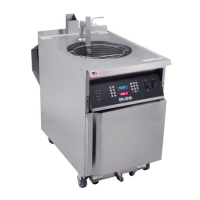
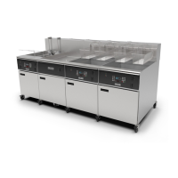
GBF-70 Fryer
5.01 Removing & Disposing of Waste Cooking Oil - continued
4. Drain oil from vat; ensure that Heat Switch remains [OFF]:
• On the unit being drained
... slowly move the drain valve handle ⑦ to the [OPEN]
position (fully right to stop). Oil should begin draining from vat. If the vat does not
readily drain, use the provided round‐bristle Drain Brush to break up residue that
might be blocking the drain.
◊ After about one‐third of the oil drains from vat, use the provided heat‐resistant Pot
Brush to rake crumbs and residue into the drain ... allow oil to completely drain
from the vat.
5. Discharging waste oil from fryer:
•
Fryer Connected to a Bulk Oil System ‐
◊
Ensure the OIL WAND valve handle ⑤ is in the [CLOSE] position (on banked system, valve is located in the left‐
hand unit with the filter pan)
. Ensure OIL RETURN valve(s) ⑥ is in the [CLOSE] position ... this valve on all
units in a banked system must be closed to prevent waste oil from returning to the vat.
◊ After all oil drains from vat, place the WASTE OIL valve ⑧ in the [OPEN] position.
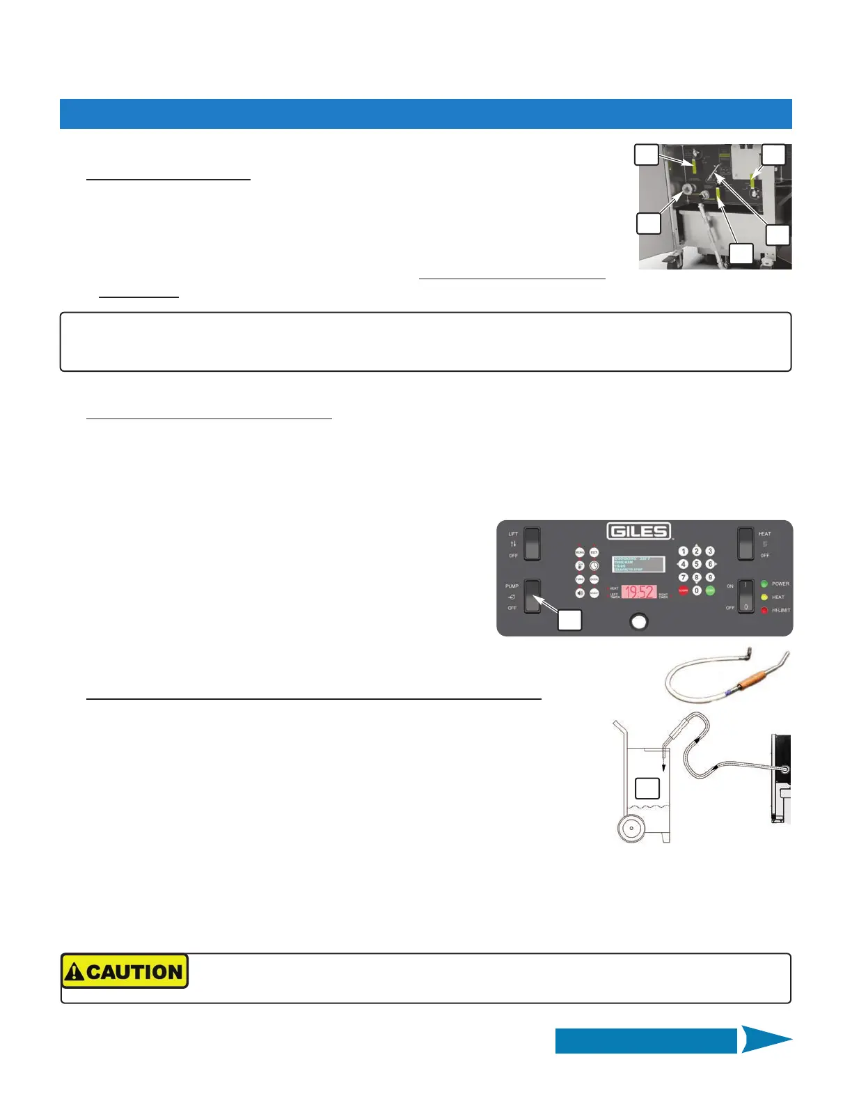
◊ Start pump by placing Pump Switch ⑪ in the [PUMP] position
(on banked systems, switch is located on left‐hand unit
control panel). Waste oil is pumped from the filter pan out to
the connected waste oil bulk collection tank.
◊ When pan is emptied, the sound of the pump will noticeably
change ... return Pump Switch to [OFF].
DO NOT allow pump to run for any extended amount of time
without oil pumping through it.
◊ Return WASTE OIL valve ⑧ to the [OFF] position.
•
Discharge Waste Oil to Protable Container (Not Provided) with Hose ‐
◊ Connect the provided Waste Oil Discharge Hose to the Discharge Hose
Coupling ⑨ inside cabinet
(on banked systems, coupling located in unit with filter
pan)
. Push in on the coupling white slip‐ring while inserting male hose fitting
and ensure the connection is secure.
◊ Place the Discharge Wand end of hose into an appropriate waste oil disposal
container ⑩ (not provided).
◊ Ensure the WASTE OIL valve ⑧ is positioned to [CLOSE].
◊ Place the OIL WAND valve ⑤ in the [OPEN] position.
◊ Start pump by placing Pump Switch ⑪ in the [PUMP] position
(on banked systems, switch is located on left‐hand
unit control panel)
. Waste oil is pumped from the filter pan through the Discharge Hose to the portable
container.
56
7
9
10
11
8
IMPORTANT!!
To avoid pump damage, should pressure build up excessively while pumping waste oil, a pressure sensor switch will
shutdown the pump until high pressure is relieved.
Continued on Next Page
When holding the hose while pumping, wear thermal protection (gloves or oven mitts).
Even with the insulating handle, some parts of the hose assembly can become very hot!
 Loading...