BlueBox
GO Systemelektronik GmbH Faluner Weg 1 24109 Kiel Germany Tel.: +49(0)431-58080-0 Fax: -58080-11
Page 14 / 77
www.go-sys.de info@go-sys.de
4 Connection of sensor and actuator
modules
The connection of sensor- or actuator modules to
the BlueBox is made by CAN
∗
(Controller Area
Net-work). The connection at
the BlueBox is a M12-male-socket (see 3.2)
In the most cases the CAN-network is built as a
line-structure. At other structures the topology of
the network has to be conform to CAN-bus.
In a line structure the first and the last unit must
be terminated (see section 4.3 Termination of the
CAN-bus).
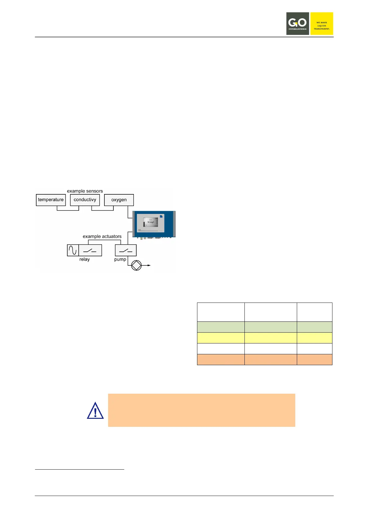
connection diagram sensors/actuators
∗
The CAN-bus (Controller Area Network) is an asyn-
chronous serial bus system and belongs to the field-
bus.
To connect a sensor-/actuator module with the
BlueBox insert the M12 male plug from the
CAN-connection cable into the M 12 female
socket at the BlueBox.
The other end of the CAN-connection cable can
be connected to a sensor-/actuator module in two
ways:
1. Connection with M12 male plug, see 4.1
Note the correct PIN assignment of the male plug
using the pin label.
When using a cable of the type LiYCY 2x2x0, 5
mm ² (article no. 339 0001), the color coding ap-
plies to the table below.
2. Connection with spring clips, see 4.2
Note the correct terminal connections using the
circuit board label.
When using a cable of the type LiYCY 2x2x0.5
mm² (article no. 339 0001), the color coding ap-
plies to the table below.
color coding cable type LiYCY 2x2x0.5 mm²
(article no. 339 0001)
PIN no.
Clip no.
color coding function
1 green (GN) CAN-High
2 yellow (YE) CAN-Low
3 white (WH) +24 V DC
4 brown (BN) 24 V GND
BlueBox T2 and elder:
If no module is connected, the BlueBox is not detected from the
BlueBox PC software.
Error message: Socket Error # 10061/Connection refused)
 Loading...