BlueBox
GO Systemelektronik GmbH Faluner Weg 1 24109 Kiel Germany Tel.: +49(0)431-58080-0 Fax: -58080-11
Page 15 / 77
www.go-sys.de info@go-sys.de
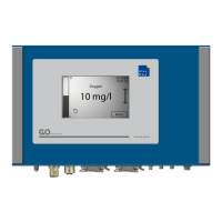
4.1 Connection via M12 male plug
As an example of connecting a sensor-/actuator
module using a 4-pin cable and two M12 connec-
tors in the following the connection of a pH sensor
as a final module is shown. At the bottom of the
sensor housing is a four-pin M12 socket. In this
the four-pin M12 male plug off the CAN connec-
tion cable is inserted and fixed by turning the un-
ion nut.
sensor connection via M12-connector
(final module)
If the sensor module should be connected as a
pass module it is made by using a Y-splitter.
sensor connection via Y-splitter
(pass module)
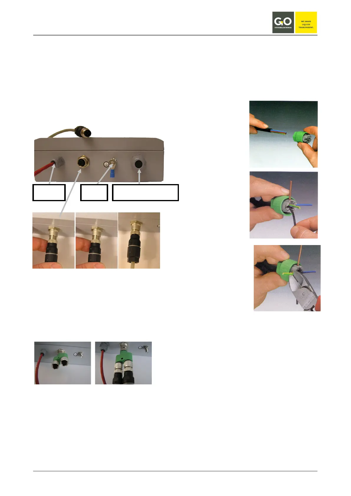
4.1.1 Mounting of the M12 male plug at
the CAN-bus cable
1. Remove the coating of the cable (approx. 40
mm)
2. Put the preas-
sembled union nut
on the cable as far
as it will go.
3. Put the cable
strand in the
marked guidance
(configuration see
the table on the
previous page).
4. Cut off the over-
laying end of the
cable strand.
exemplary connection of a M 12 plug
with a 4-PIN cable
CAN-bus connecting cables or connectors can be
ordered by us under the following article numbers.
Article no.:
Cable for data and supply 339 0001
M 12 male plug 338 1100
M 12 Y-splitter 338 1500
earthing
optional sensor connection
pH sensor
 Loading...