BlueBox
GO Systemelektronik GmbH Faluner Weg 1 24109 Kiel Germany Tel.: +49(0)431-58080-0 Fax: -58080-11
Page 9 / 77
www.go-sys.de info@go-sys.de
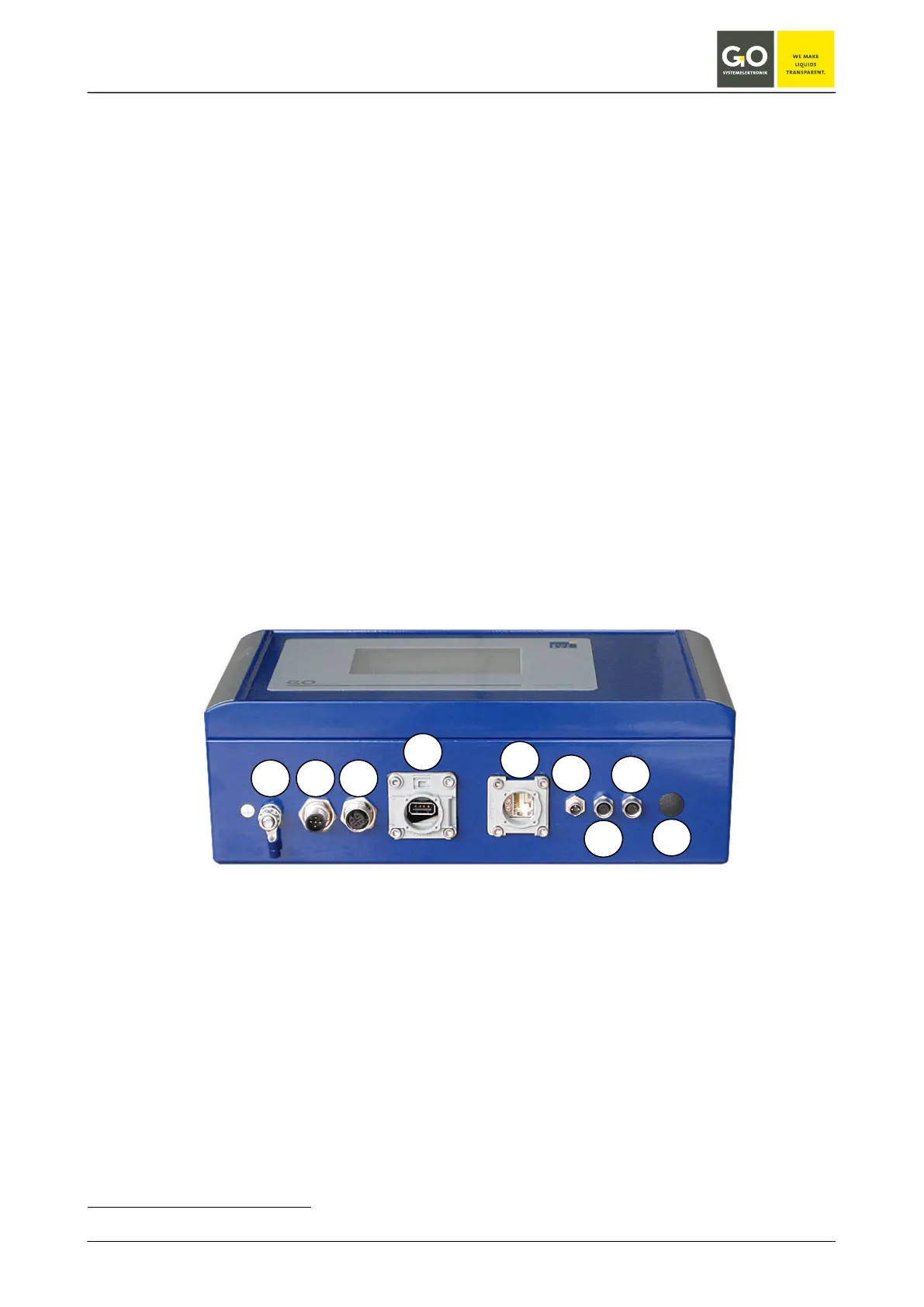
3.2 Connection options
The BlueBox has the following connection options:
1. Ground connection
2. Power supply (24 V DC) via a 5-pin M12 panel plug (male)
3. Connection CAN-bus via a 5-pin M12 panel jack (female)
CAN-bus connection to the BlueBox sensor-/actuator modules via 4-wire CAN-Bus connection cable
4. USB connection
Please note: The USB port on the BlueBox is provided for data storage and update the firmware.
5. LAN port for LAN cables in standard or cross-link design (see also 3.4).
6. Connection serial interface via a 3-pin M8 panel plug (male), RS-232 or RS-485
7. Connection current output
∗
4 to 20 mA via a 4-pin M8 panel jack (female)
8. Connection current output* 4 to 20 mA via a 4-pin M8 panel jack (female)
9. Hole for an antenna or cable modem
Modems (optional):
• UMTS modem with antenna
• analogue modem
• ISDN modem
∗
optional
 Loading...