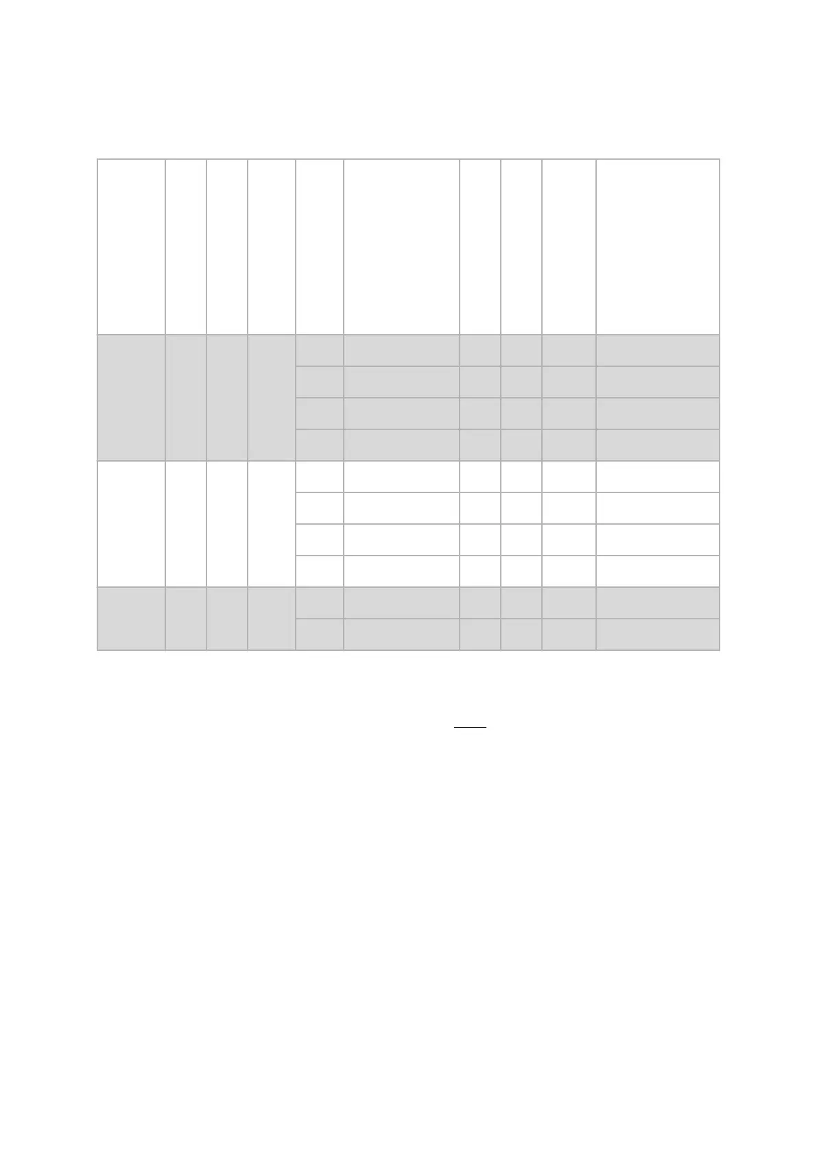
Sensor Configurations
Camera Support
Slider Distance [mm]
Camera Angle [°]
Measuring distance [mm]
Measuring Volume Name
Measuring Volume [mm³]
Focal Length
Aperture
Reference Point Size
in Full Screen Mode [mm]
Calibration Object
500/800 135 25 393
70 70 x 50 x 20 75 22 0.4 CP40/MV100
130 130 x 100 x 40 50 16 0.4 CP40/MV170
200 190 x 150 x 60 35 11 0.8 CP40/MV170
300 290 x 230 x 200 24 11 0.8 CP40/MV320
500/800 268 25 693
170 165 x 125 x 40 75 16 0.4 CP40/MV170
260 260 x 200 x 80 50 11 0.8 CP40/MV320
400 380 x 290 x 200 35 11 1.5 CP40/MV320
550 550 x 440 x 400 24 8.0 1.5 CC20/MV500
800 580 25 1396
600 570 x 440 x 400 50 8.0 1.5 CC20/MV500
1200 1170 x 940 x 940 24 4 3.0 CC20/MV1400
Tab. 2: ARAMIS Adjustable SRX
4.4.2 Further Configuration Examples
The sensor configuration table Fig. 3 shows how to set up dierent meas‐
uring volumes with a set of camera lenses.
System Overview
0000001503_002_EN_02-12-2019 Page 14 (56)