The system measures 3D coordinates over time. From the 3D coordinates,
displacements, strains and derived values such as velocities or accelera‐
tions are computed.
The first image in the measuring project represents the initial state of the
object. To compute the displacement of the pattern marks to each other,
the software compares the coordinates computed during the measuring
procedure.
3.1 Typical Measuring Procedure
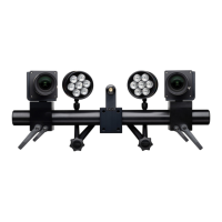
You can position the ARAMIS Adjustable system freely on a stand. If you
use a 3D measuring setup, use two cameras (stereo setup). You must cali‐
brate both cameras before measuring. You create the measuring project in
the software. Then, you capture the images in various load stages of the
specimen.
After successful computation, the measuring result is available as 3D view.
All further result representations like statistical data, sections, reports, etc.,
are derived thereof.
Brief Introduction to the ARAMIS System
0000001503_002_EN_02-12-2019 Page 9 (56)