11 Cabling
Info
During cabling, the devices must be switched o. Ensure that all devices
are wired before you apply the supply voltage.
Follow the starting sequence of the individual components to ensure a
functioning system.
•
Start the measuring computer.
•
Start the GOM Testing Controller. The cameras are started via the
GOM Testing Controller. The GOM Testing Controller transmits the rel‐
evant signals to the sensor connection hub.
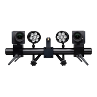
11.1 Cabling of ARAMIS Adjustable
11.1.1 Cabling of ARAMIS Adjustable SRX
Info
Not all components shown in the cabling plan are included in the stand‐
ard scope of supply of the ARAMIS Adjustable SRX sensor.
Info
If you use the system for 2D measuring projects, only one camera is availa‐
ble.
The lighting shown in all illustrations is optional.
0000001503_002_EN_02-12-2019
Page 52 (56)