10 Calibrate the Sensor
A calibration is a measuring process in which a calibration object is meas‐
ured. Thus, the measuring system is adjusted and its dimensional consis‐
tency is ensured. During this process, the software determines geometrical
parameters, for example position and orientation of each camera, based
on the recorded camera images. Furthermore, the software determines
the image characteristics of the camera lenses and of the camera chip.
These settings are the computation basis of the software. From the points
of the calibration object in the 2D camera image, the software computes
the 3D coordinates of the points.
The software then calculates the 3D coordinates back again into the 2D
camera images. For the position of the reference points, this results in the
reference point deviation (intersection error).
Generally, each measuring volume (MV) has its own calibration object. The
table in section
4.4 informs you about which calibration object is required
for your measuring volume.
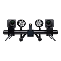
With a stereo camera setup (3D measuring projects), the measuring sys‐
tem must always be calibrated.
If you use a measuring system with only one camera (2D measuring
projects), calibration with a calibration object is not strictly necessary.
However, the software cannot include the image characteristics of the
camera lenses (distortion) and of the camera chip when computing the
coordinates.
For simple evaluations, such as measuring displacements or velocities, this
inaccuracy may be negligible. To evaluate your data, you must manually
set the appropriate scale bar parameters in the software.
Info
Refer to the direct help information on this topic in the software: Define
Scale.
Ensure a correct test setup. The camera must be oriented vertically
towards the measuring object.
When calibrating with a calibration object, the software can include the
image characteristics of the camera lenses (distortion) and of the camera
chip when computing the coordinates. This way, you receive more accu‐
rate measuring results.
Info
Check the measuring distance. Ensure that the measuring distance is
appropriate both between the calibration object and the camera and
between the measuring object and the camera.
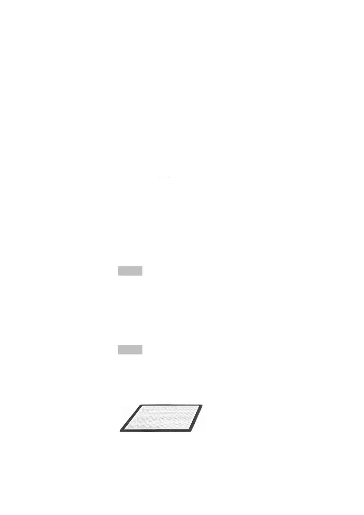
For the ARAMIS Adjustable measuring volumes, dierent calibration
objects are available.
Fig. 20: Calibration panel CP40 with magnetic support (e.g. for MV170)
0000001503_002_EN_02-12-2019 Page 34 (56)