Air Caps and Fluid Nozzles
Air Caps and Fl
uid Nozzles
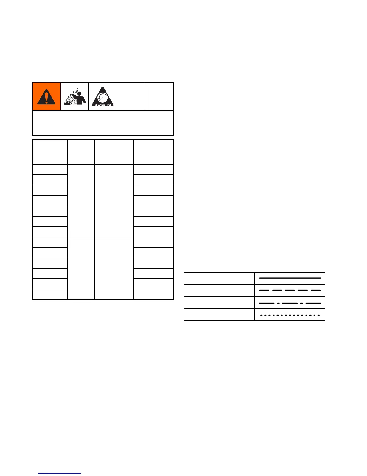
Fluid Nozzle S
election Chart
To reduce the risk of an injury, follow the
Pressure Relief Procedure, page 27, before
removing or installing a fluid nozzle and/or air cap.
Fluid
Nozzle
Part No.
Color
Description
Orifice Size
mm (in.)
24N613
0.75 (.029
)
24N614
1.0 (.042)
24N615
1.2 (.047)
24N616
1.5 (.05
5)
24N617
1.8 (.070)
24N618
2.0 (.079)
24N619
Black
For
standard
coatings
0.55 (
.022)
24N620
0.75 (.029)
24N6
21
1.0 (.042)
24N622
1.2
(.047)
24N623
1.5 (.055)
24N
624
1.8 (.070)
24N625
Blue
With
hardened
seat, for
abrasives
and
metallics
2.
0 (.079)
Fluid Nozzle P
erformance Charts
Use the following procedure to select the proper fluid
nozzle for your application.
1. For each flui
d nozzle chart, find the point on the
graph corre
sponding to your desired flow rate
and viscosi
ty. Mark the point on each graph with
a pencil.
2. The thick v
ertical line in each graph represents
the target
flow rate for that nozzle size. Find
the graph t
hat has the marked point closest to
the thick v
ertical line. This is the recommended
nozzle siz
e for your application. Significantly
exceedin
g the target flow rate may result in
lower spr
ay performance due to excessive fluid
velocity
.
3. From the m
arked point, move across to the
vertica
l scale to find the required fluid pressure.
If the re
quired pressure is too high, use the next
largest
nozzle size. If the fluid pressure is too low
(< 0.35 b
ar, 3.5 kPa, 5 psi), use the next smallest
nozzle s
ize.
Key to Fluid Nozzle Performance Charts
NOTE: Fluid pressures are measured at the spray
gun inlet.
260 Centipoise Fluid
160 Centipoise Fluid
70 Centipoise Fluid
20 Centipoise Fluid
68 3A2494E