Gun Overview
Controls, Ind
icators, and Components
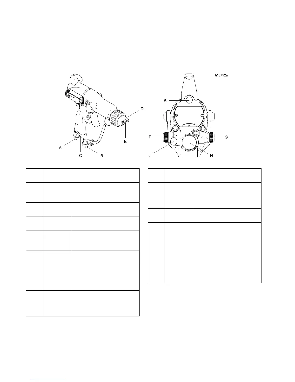
The electrostatic gun includes the following
controls, indicators, and components (see Fig.
1). For information on Smart guns, also see
Smart Guns, page 9 .
Figure 1 Gun Overview
Item Descrip-
tion
Purpose
A
Air Swivel
Inlet
1/4 npsm(m) left-hand thread,
for Graco grounded air supply
hose.
B Fluid Inlet
3/8 npsm(m), for fluid supply
hose.
C
Turbine Air
Exhaust
Barbed fitting, for supplied
exhaust tube.
D
Air Cap
and
Nozzle
See Air Caps and Fluid
Nozzles, page 68, for avail-
able sizes.
E Electrode
Needle
Supplies electrostatic charge
to the fluid.
FFanAir
Adjust-
ment
Valve
Adjusts fan size and shape.
Canbeusedtodecrease
pattern width.
G
Atomizing
Air
Restrictor
Valve
Restricts air cap air flow.
Replace with plug (included)
if desired.
Item Descrip-
tion
Purpose
H Fluid Ad-
justment
Knob
Adjusts fluid flow by limiting
fluid needle travel. Use only
in low flow conditions, to
reduce wear.
J
ES On-Off
Valve
Turns electrostatics ON (I) or
OFF (O).
K
ES Indica-
tor (stan-
dard gun
only; for
Smart gun
indica-
tor, see
Operating
Mode,
page 9 )
Lit when ES is ON (I). Color in-
dicates alternator frequency.
See the LED indicator table
in the Gun Setup Checklist,
page 18.
8 3A2494E