-32-
Model G1026 (Mfd. Since 10/13)
The fence assembly is a two-piece, independently
adjustable system. When removing material from
the whole face of your workpiece, the outfeed
fence can be adjusted to provide support for the
workpiece as it passes over the cutter, or it can be
set up for partial face removal.
When removing material from the entire board
face, observe the following steps:
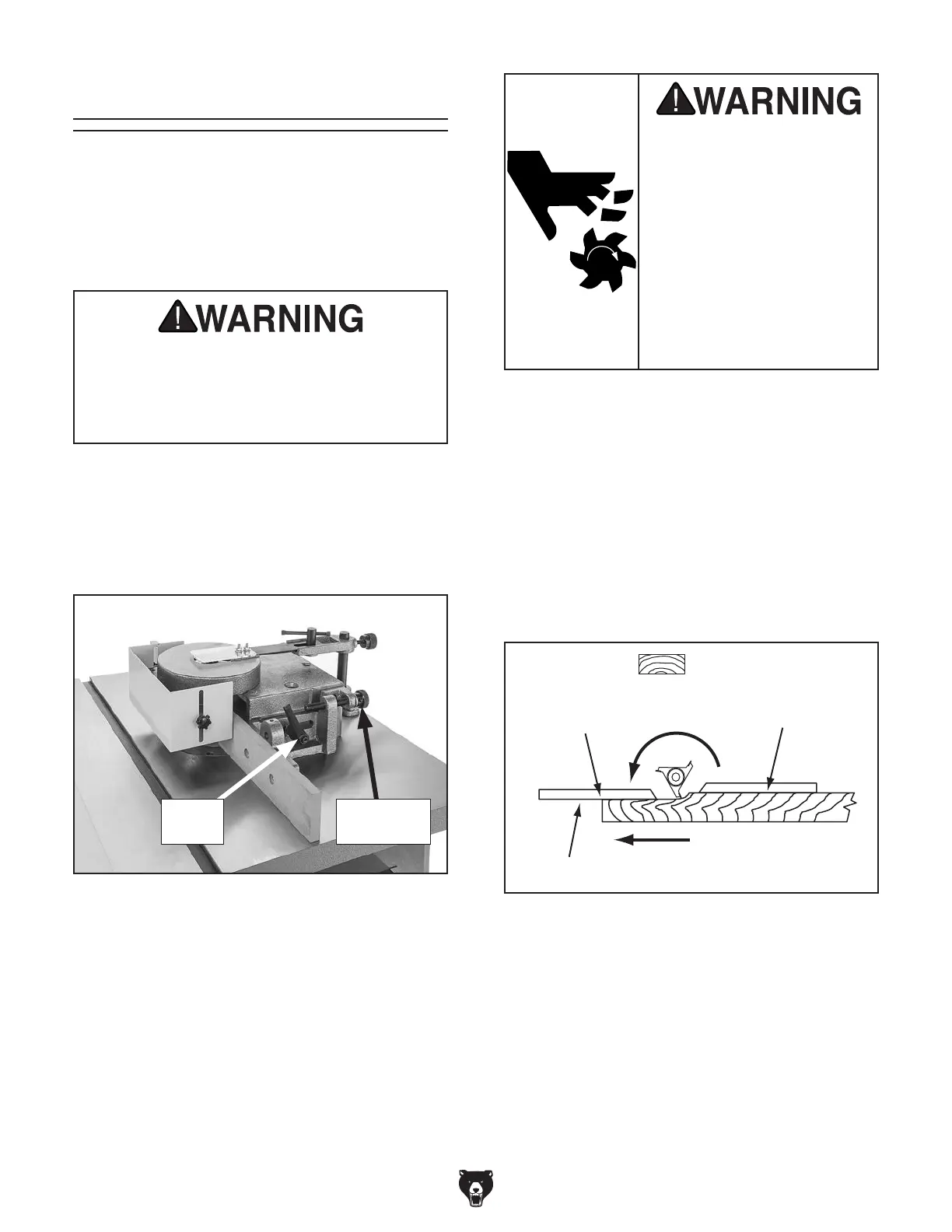
1.
Loosen the locking handles that hold the
fences in place (see Figure 41).
4.
Lock the infeed fence in position with the lock
handle.
5. Turn the shaper ON and advance a test
sample of the desired cut about 8'', then stop.
Swing the test piece away from the cutter and
turn the machine OFF.
6.
When the cutter comes to a complete stop,
adjust the outfeed fence to support the new
profiled edge, as shown in Figure 42.
Figure 41. Fence adjustments.
Straight Shaping
Attempting to operate the shaper without
proper knowledge of the machine could
cause serious injury or death! Read through
the entire manual carefully before attempt-
ing to make any cuts with your shaper.
2. Adjust the infeed fence by turning the knurled
adjustment knob until the workpiece contacts
the cutter in the desired location.
3.
Use a test piece at least 24" long to deter-
mine the best setting.
Figure 42. Support workpiece as it is fed.
End View
Direction of Feed
Outfeed
Fence
Supported
Infeed
Fence
All guards MUST be
installed on shaper before
operating it. Shapers are
dangerous machines that
can quickly cause serious
injury if some kind of guard
is not used. To protect
yourself, read and follow
entire instruction manual
carefully and do addition-
al research on shop made
guards and safety jigs.
Lock
Handle
Adjustment
Knob
 Loading...