-4-
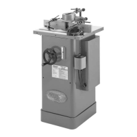
Model G1026 (Mfd. Since 10/13)
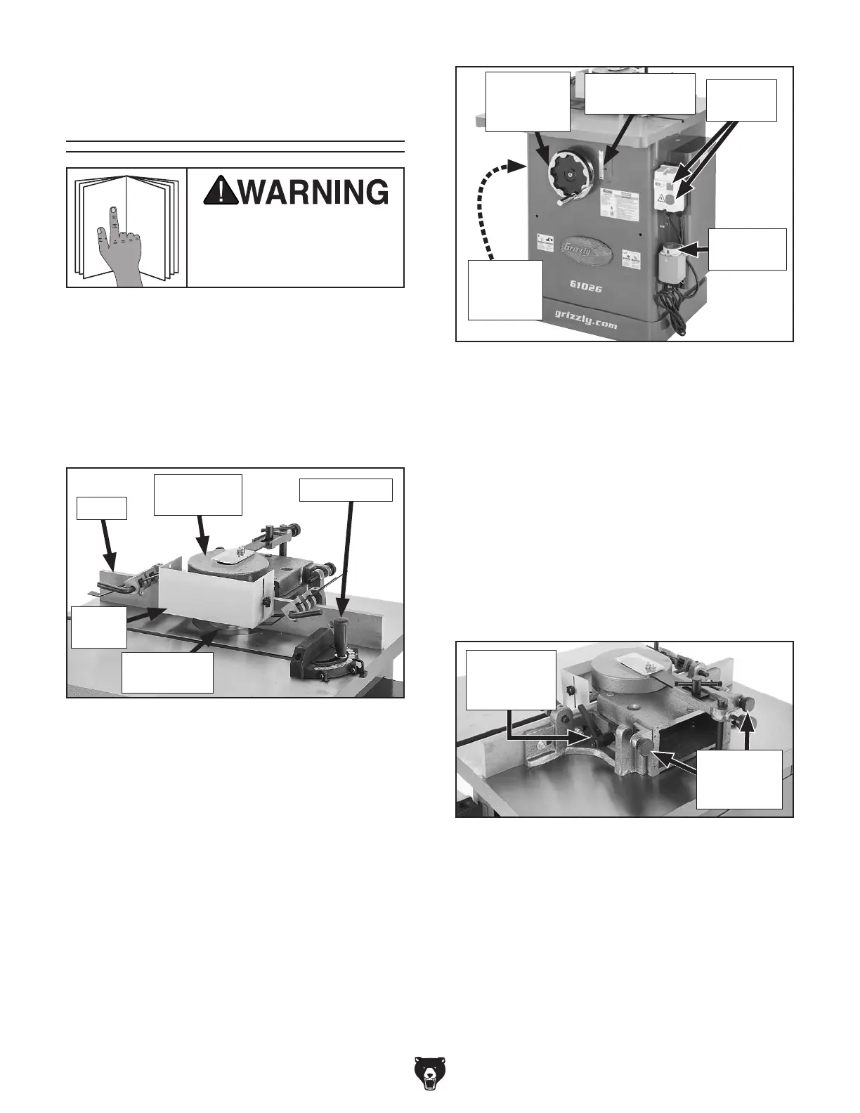
Controls &
Components
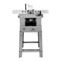
Figure 3. Work area components.
Spindle Elevation Handwheel: Raises and low-
ers spindle and cutter to desired height.
Spindle Height Scale: Displays the height posi-
tion of the spindle in inches.
ON/OFF Switch: Turns machine ON and OFF.
Forward/Reverse (FOR/REV) Switch: Starts,
stops, and reverses spindle rotation.
Spindle Elevation Lock (not shown): Locks
spindle and bit height adjustments.
Spindle
Elevation
Lock
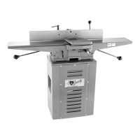
Figure 4. Fence controls.
Fence Lock Handles: Tighten to lock fence posi-
tion on table.
Fence Adjustment Knobs: Move each fence
independently relative to cutterhead. One turn
moves each fence approximately
5
/64" (.078").
FOR/REV
Switch
ON/OFF
Switch
Spindle Height
Scale
Spindle
Elevation
Handwheel
Fence
Adjustment
Knobs
Fence Lock
Handle
(1 of 2)
To reduce your risk of
serious injury, read this
entire manual BEFORE
using machine.
Refer to the following figures and descriptions to
become familiar with the basic controls and com-
ponents of this machine. Understanding these
items and how they work will help you understand
the rest of the manual and minimize your risk of
injury when operating this machine.
Work Area Controls
Figure 2. Work area components.
Fence
Miter Gauge
Fence: Each fence is independently adjustable
side-to-side and front to back. Also removable for
easy replacement with a zero-clearance or other
custom-made fence.
Cutterhead and Safety Guards: Adjust to pro-
tect user from chips thrown by cutterhead.
Miter Gauge: Supports workpiece for controlled
straight or angled cuts as it slides along the work
table miter slot.
Starting Pin (not shown): Supports workpiece
during beginning of freehand cuts until workpiece
contacts rub collar (refer to Page 35).
Starting Pin
Location
Cutterhead
Guard
Safety
Guard
 Loading...