Model G1026 (Mfd. Since 10/13)
-19 -
Each of the three spindles that come with the
Model G1026 is sized to work efficiently with dif-
ferent sized cutters and spacers. The spindles
must be inserted correctly and remain securely
locked in the machine in order to produce qual-
ity work. When installing and changing spindles,
make sure the spindle seats snugly and that there
is enough drawbar threaded into the bottom of the
spindle to safely secure it in place.
To install a spindle:
1.
Remove the hex nuts from the spindle and
the drawbar nut from the drawbar.
2. Thread the drawbar approximately 10-15
turns into the bottom of the spindle. The
drawbar has two threaded ends. One of them
remains exposed (see Figure 14).
Figure 14. Spindle and drawbar.
10-15 Turns
Spindle
Drawbar
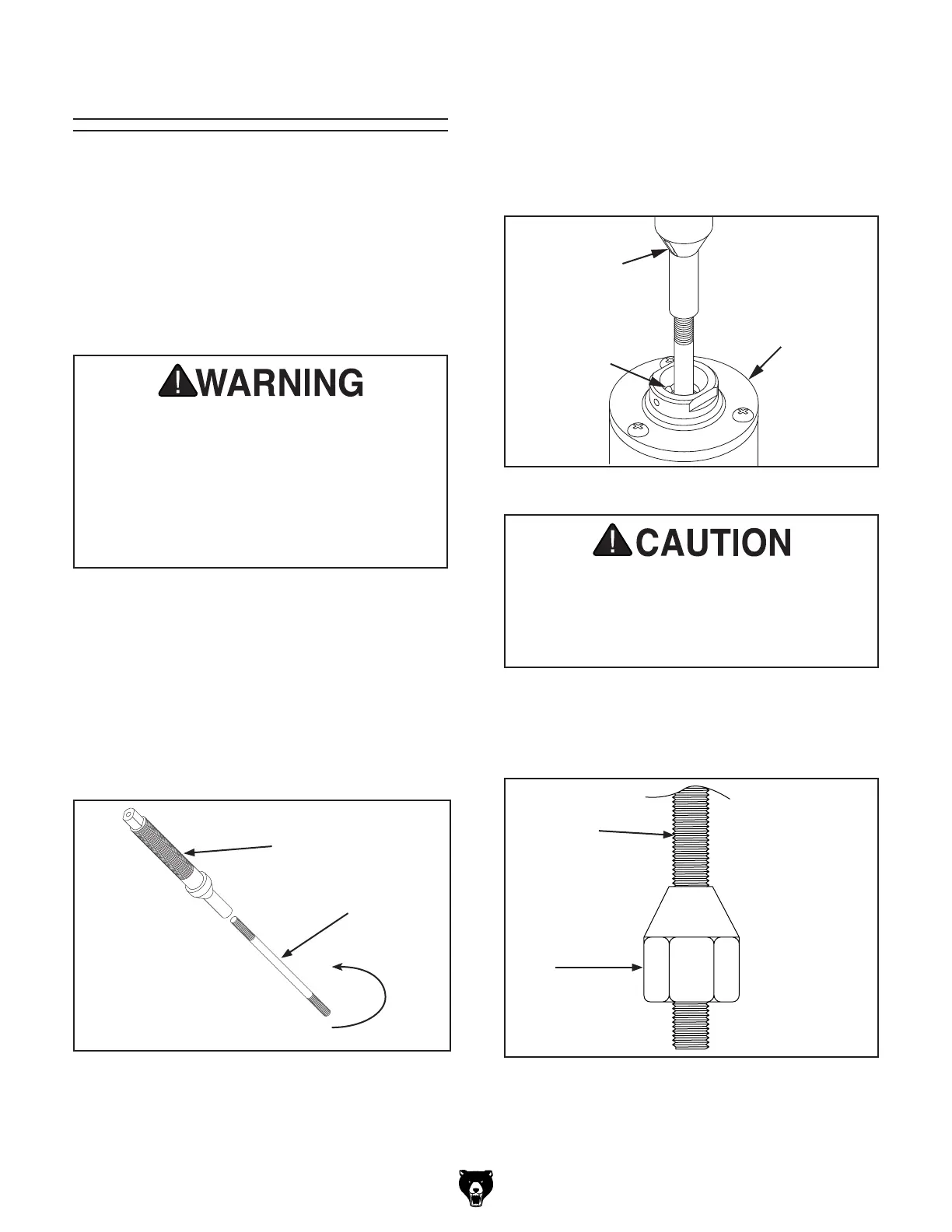
3.
Place the spindle/drawbar into the spindle
cartridge at the top of the table. Line up
the keyway on the spindle with the locating
pin at the top of the spindle cartridge (see
Figure 15). You will feel the spindle seat
itself.
Incorrect assembly can allow the spindle
and cutter to fly off the machine, which
could cause injury or death. Make certain
the spindle is properly assembled before
operating the Shaper. If you are uncertain of
any aspect of this assembly, please review
these instructions again or contact our
Customer Service.
Spindle
Keyway
Pin
Spindle
Cartridge
Figure 15. Inserting the spindle into place.
4. Thread the drawbar nut, tapered side up, onto
the bottom of the drawbar until it stops below the
spindle housing cartridge (see Figure 16).
Figure 16. Nut threaded onto drawbar.
Make sure the spindle keyway and pin are
aligned and properly seated before tighten-
ing the drawbar nut. Improper assembly can
create an unsafe condition and possible
injury to the operator.
Drawbar
Nut
 Loading...