3
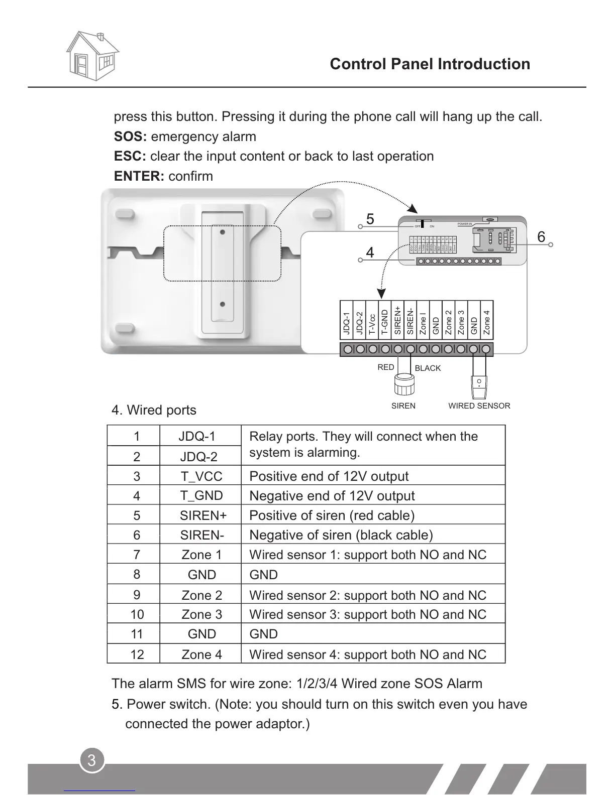
4. Wired ports
Control Panel Introduction
6
JDQ-2
T-Vcc
T-GND
SIREN+
SIREN-
Zone l
GND
Zone 2
Zone 3
GND
Zone 4
JDQ-1
RED
SIREN WIRED SENSOR
10
11
12
JDQ-1
JDQ-2
T-Vcc
T-GND
SIREN+
SIREN-
Zone1
GND
Zone2
Zone3
GND
Zone4
1
2
3
4
5
6
7
8
9
OFF ON
POWER IN
press this button. Pressing it during the phone call will hang up the call.
SOS: emergency alarm
ESC: clear the input content or back to last operation
ENTER: confirm
The alarm SMS for wire zone: 1/2/3/4 Wired zone SOS Alarm
5. Power switch. (Note: you should turn on this switch even you have
connected the power adaptor.)
1
JDQ-1
Relay ports. They will connect when the
system is alarming.
2 JDQ-2
3
T_VCC Positive end of 12V output
4
Negative end of 12V output
5
SIREN+
Positive of siren (red cable)
6
SIREN-
Negative of siren (black cable)
7
8
9
10
11
GND
GND
12
T_GND
Zone 1
Wired sensor 1: support both NO and NC
GND
GND
Zone 2 Wired sensor 2: support both NO and NC
Zone 3 Wired sensor 3: support both NO and NC
Zone 4 Wired sensor 4: support both NO and NC
BLACK