5.3.3 Setting output voltage
The output voltage settings listed below can be made for the two operation modes.
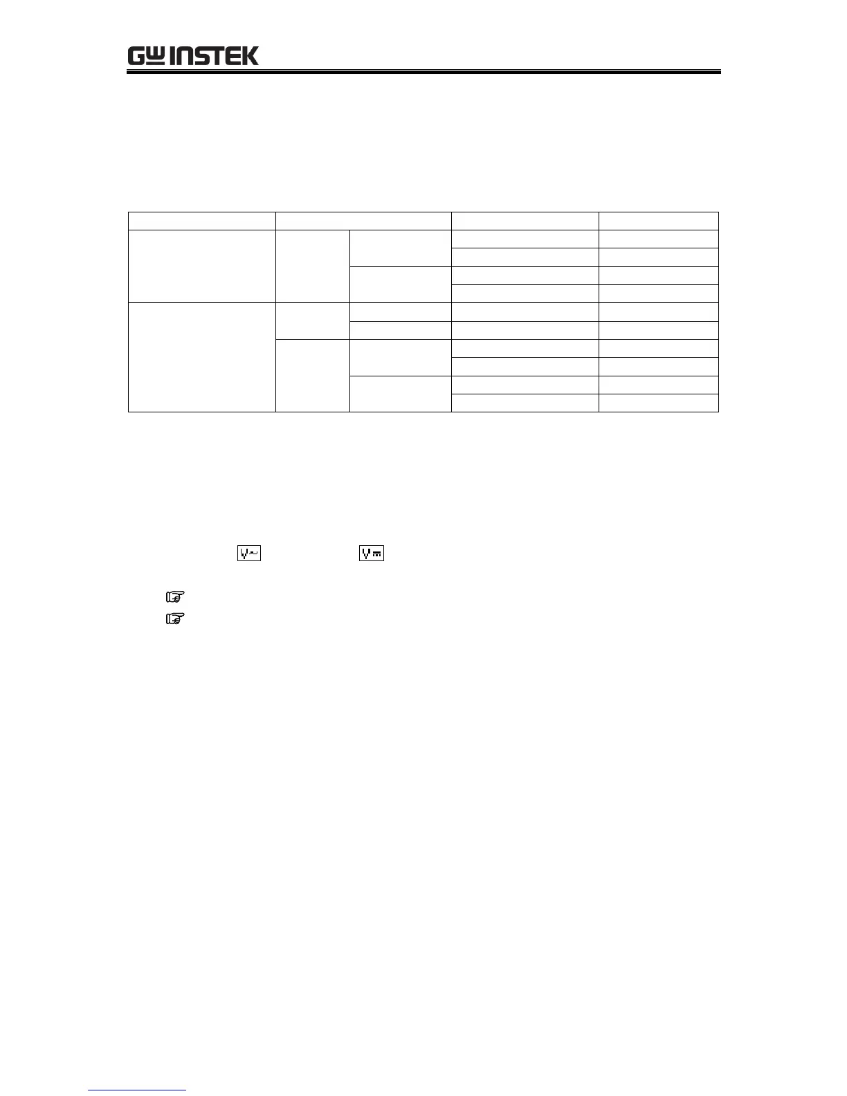
Table5-13. Output Voltage Settings
When the selected AC voltage waveform is either SIN (sine wave) or SQU (square wave), the AC voltage
setting is made in Vrms units. When it is ARB (arbitrary waveform) 1 to 16, this setting is made in Vp-p
units.
Operation steps
Select either “AC voltage” or “DC voltage” in the output voltage SET menu then set a
numerical value.
See “3.4.5 Setting output voltage”, for description of output voltage setting.
See also “4.1.4 Setting the output voltage”.
 Loading...