4.4.6 Example of sequence operation settings
The following describes the steps for setting a new sequence operation, based on the sequence transition
example described in Table4-12. The time unit is seconds (s). ( See “5.6.5 Time unit setting” to
change the time unit.)
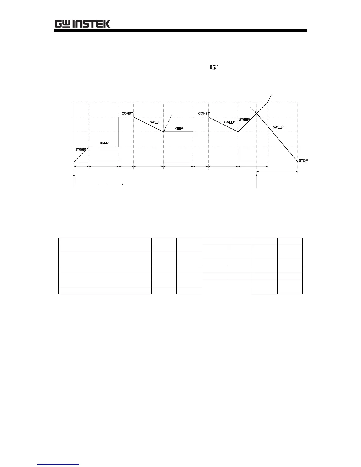
Figure 4-13. Step Transition Example (during AC+DC-INT mode)
Table4-12. Program Settings
Though the DC voltage of step 2 is set to 75.0 V, the output DC voltage will be 25.0 V which is succeeded
from the previous step (step 1) because the DC operation type of step 2 is set to KEEP. After executing
step 4, the sequence will jump to step 2 because the jump step of step 4 is set to 2 (<1> in Figure 4-13).
The output DC voltage will be kept to 50.0 V coming from the previous step (step 4) because the DC
operation type of step 2 is set to KEEP. The jump times of step 4 is set to 1, so the sequence will move to
the next step (= step 5) after jumping once and executing step 4 (<2> in Figure 4-13). The step time of
step 5 is set to 0.2 s and the branch 0 jump step of step 5 is set to step 6, so the sequence will immediately
move to step 6 when the branch 0 is input within the step time (<3> in Figure 4-13).