6.5.2 Standard event status
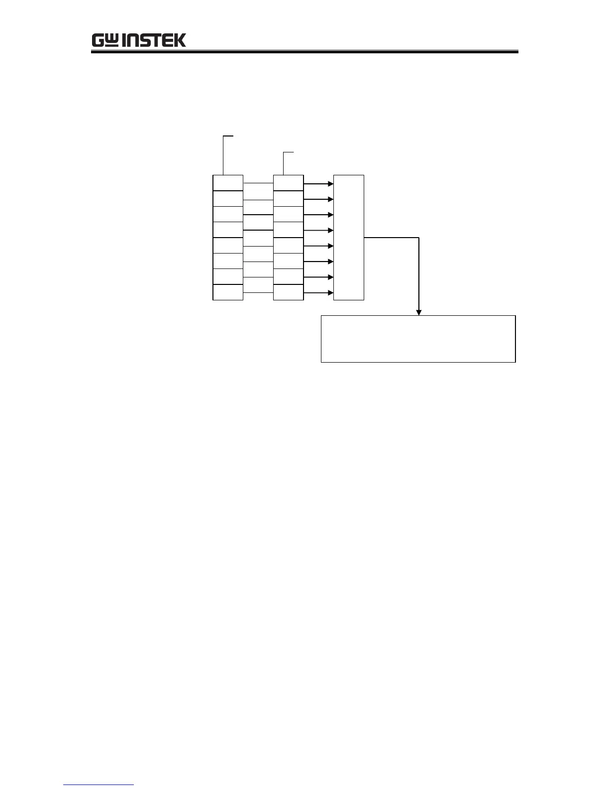
The structure of the standard event status register is shown in Figure 6-5 below.
Figure 6-5. Standard Event Status Register
The definition of the standard event status register is listed in Table6-15. Bits in the standard event status
register become valid when 1 is set to the standard event status enable register, and the ORed result of the
valid bits is reflected in the ESB bit of the status bit register.
The standard event status register can be read by an ESR? query.
All of the bits are cleared when they are read by an *ESR? query, when a *CLS command is executed, or
when the power is turned on again (except that the PON bit is set to 1 when the power is turned on again).
 Loading...