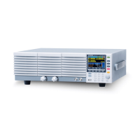
External resistance control of the CC, CR, CV and
CP modes is accomplished using the J1 connector
on the rear panel.
A resistance of 0kΩ-10kΩ is used to control the
input current, voltage, resistance or power on the
PEL-3000(H).
The input can be configured to vary in proportion
to the external resistance or the inverse. See page
174 for more details on proportional and inverse
resistance control.
Exceeding 11.8kΩ will cause an EXT.OV alarm
message which will reset the voltage output to 0 until
the external resistance is reduced back down below
11.8kΩ.
When connecting the external resistance source to
the J1 connector, use a ferrite core and use twisted
pair wiring.

 Loading...
