MM-013994-001, Rev. J
20
In Conventional Analog mode, the user selects a channel and communicates directly on that channel. A
channel is a transmit/receive radio frequency pair.
The exact operation of the radio depends on the operating mode, the radio’s programming, and the
particular radio system. Most features described in this manual can be enabled through programming.
Consult your System Administrator for the particular features programmed into your P7300. Then refer
to the corresponding section(s) within this manual for feature and operation information.
6.1 WEATHERPROOF
The P7300 series radios operate reliably under adverse conditions. These portable radios meet military
standards MIL-STD-810F specifications for high and low operating and storage temperatures, low
pressure extremes, thermal shock, solar radiation, driven rain, humidity, salt fog, blowing dust, shock, and
vibration.
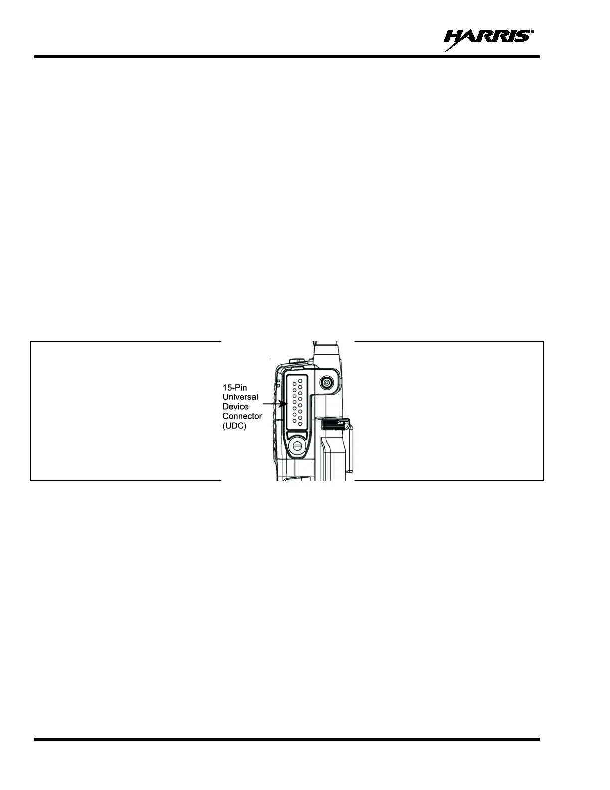
6.2 UNIVERSAL DEVICE CONNECTOR
The Universal Device Connector (UDC) provides connections for external accessories such as a headset,
a speaker-microphone, audio test box, audio test cables, and programming cables. The UDC is located on
the right side of the radio, opposite the PTT Button. The UDC facilitates programming and testing the
radio. The UDC pins perform different functions depending on the accessory attached to the UDC.
Figure 6-2: P7300 15-Pin Universal Device Connector
 Loading...