17
After the unit has been installed, mounted and
powered you can now enter the Quickstart settings to
get the unit operational in your application conditions.
Be sure to enter settings for High & Low level, App
Type, Fill Rate and Empty Rate of your vessel.
If you are unsure of your specific fill & empty speed
enter a value you are sure is faster than your process.
All of the mentioned settings (except Blanking) are
in the ‘Quickset’ menu of the unit. You access
this menu on the control pad by pressing CAL and
entering Unlock code 0.
You may also need to set relay switch points. These
are found in ‘Output Adjustment’. Relay alarms can
be set on/off for hi/lo levels and failsafe.
Setting Your System
Sultan Acoustic Wave Series
(A)
Blanking
zone
(B)
(C)
(D)
(E)
Space
Material
Low
Level
High
Level
Adjust vessel low level (maximum measured
distance from transducer face)
Adjust vessel high Level (minimum
measured distance from transducer face)
Feet
Metres
Centimeters
Inches
QuickSet
Unit
Low Level
High Level
Position
Slurry
Solids
Liquids
App Type
Empty Rate
Fill Rate
Adjust
vessel
fill rate
Adjust
vessel
empty rate
Fail Safe
3.50mA
3.80mA
20.20mA
Last Known
Adjust
Fail time
(seconds)
Fail Time
CAL
Display Mode
CAL
CAL
CAL
CAL CAL
CAL
CAL
CAL
CAL
CAL
Avg Matrl
Diff O/P
Space
Material
CAL
Material%
Flow
Volume
Flow Tbl
Select unit of
measurement from
Fill Rate
Empty Rate
Select FailSafe
mA output
Note: If using GosHawk PC
comms you must change fill
& empty rate AFTER selecting
app type.
Filling damping.
Number of pulses
averaged for output
Fill Damp
Output Adj
Empty Damp
Rly Mode 1
Adjust Empty Damping
Set Relay
Level 1 &
DEN
EN
FS
OFF
CAL
CAL
Rly Modes 2-5
CAL
CAL
RlyL1
RlyL2
CAL
Relay Triggers - Denergise,
Energise, Fail Safe, Off
Example EN
L1 = relay OFF point
L2 = relay ON point
Example DEN
L1 = relay ON point
L2 = relay OFF point
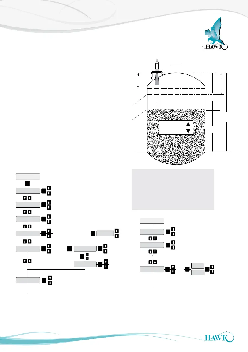
(A) Transducer Face - Top of Flange
(B) End of Blanking Zone
(C) High Level or 100% (20mA) position.
(D) Product Level being measured
(E) Low Level or 0% (4mA) position.
High Level = Distance A to C
Low Level = Distance A to E