5
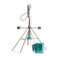
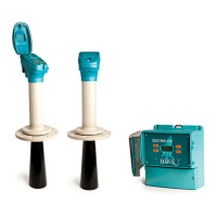
Sultan Remote Units
The Sultan Remote amplier has wiring information printed inside the ip lid of the unit.
Unscrew the lower flip lid to access the wiring
terminals.
Ensure your power source is deactivated before
handling power wires.
Pass cables through the cable entry gland before
wiring into the terminal block.
To connect a wire, remove the required terminal
block with pliers place the wire in firmly screw down
the connection. The transducer terminals are labeled
by colour on the PCB.
If you are connecting HawkLink communications,
connect the blue wire to B and the white wire to A.
The black wire can be connected to the DC- or GND
terminal next to A.
Tighten cable entry gland(s) and cover to ensure
sealing is effective.
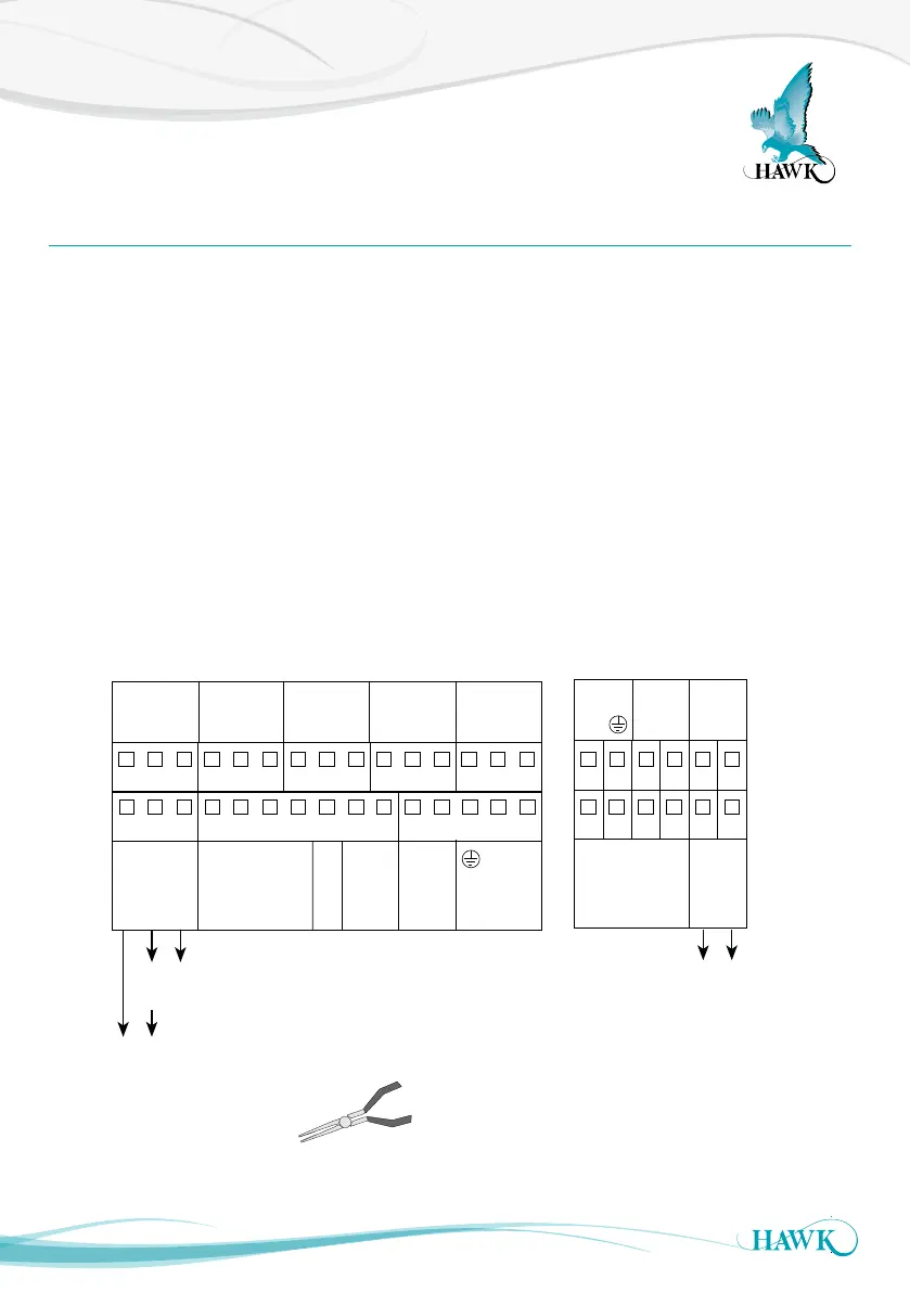
Wiring The Unit
Sultan Acoustic Wave Series
Sourcing 4-20mA from Sultan
Sinking 4-20mA
from user device
OR
+
–
A
1L
+
–
N
B
RED
BLACK
BLUE
WHITE
Test In
Is
TRANSDUCER DC-In AC-In*4-20mA
COMMS
RELAY 1
NC
COM
NO
RELAY 2
NC
COM
NO
RELAY 3
NC
COM
NO
RELAY 4
NC
COM
NO
RELAY 5
NC
COM
NO
1 2 3 4 5 6 7 8 9 10 11 12 13 14 15
16 17 18 19 20 21 22 23 24 25 26 27 28 29 30
B
RED
BLACK
BLUE
WHITE
Test In
TRANSDUCER
COMMS
+
–
4-20mA
A
Shld
Shld
Sinking 4-20mA
from user device
1 2 3 4 5 6
7 8 9 10 11 12
*AC-In is replaced by 36-60VDC with
Power Input Option ‘C’.
234 wire version 2 wire version
Use long nose pliers to extract terminals