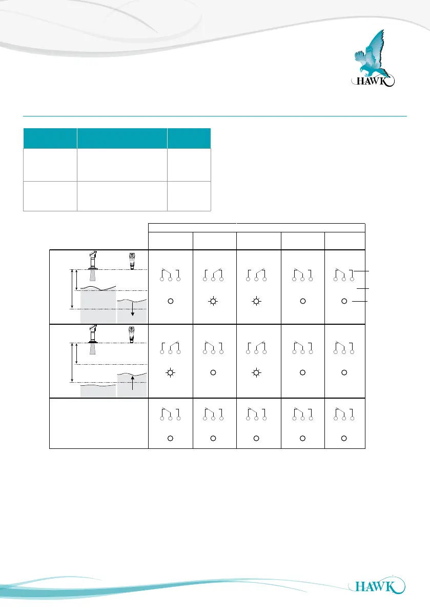
Relay Switch Actions
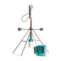
Sultan Acoustic Wave Series
34
Relay 1 - 5
• Set Relay Parameters in Output Adjustment menu
• The two relay levels are RlyL1 and RlyL2
• The display will show RlyL1 1, the last 1 indicated
the Relay number (eg 1 to 5)
• L1 and L2 distances are measured from the
transducer face
Sub-Menu Description Options
Rly L1 1- 5
Adjust Relay switch point
(L1 must be < L2)
Adjustable
RlyL2 1-5
Adjust Relay switch point
(L2 must be > L1)
Adjustable
HI
OFF
TEST
LOW
EN
DEN
CAL
OFF
DELAY
SENSITIVITY
Energise
EN
DeEnergise
DEN
COMMS DC-IN
AC GND to metal case
12-30VDC
+
7.
8.
RS 485
5.
B
6.
A
1 2 3 4 5 6 7 8 9 10
+
–
4-20mA
AC-IN
A
1L
+
–
DC-I N
4-20mA
COMMSTRANSDUCE R
N
B
RELAY 1
NC
COM
NO
RELAY 2
NC
COM
NO
RELAY 3
NC
COM
NO
RELAY 4
NC
COM
NO
RELAY 5
NC
COM
NO
Test in
Is
RED
BLACK
BLUE
WHITE
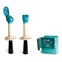
REMOTE AMPLIFIER
GLADIATOR TERMINAL
NC NOCOM
NC NOCOM
NC NOCOM
POWER FAILURE
State 1
State 2
Relay Action
FailSafe
FS
FailSafe
FS
NC NOCOM
Relay Status
LED Status
Remote Amplifier
terminal function
labels
NC NOCOM
NC NOCOM
NC NOCOM
NC NOCOM
NC NOCOMNC NOCOM
NC NOCOM NC NOCOM NC NOCOM NC NOCOM NC NOCOM
system operating
normally
OFF
power/system/
measurement failure
Below L2 or
RISING LEVEL
L1
L2
between L1 and
L2 after passing
below L2.
LOW LEVEL or
Above L1 or
FALLING LEVEL
L1
L2
between L1 and
L2 after passing
above L1.
HIGH LEVEL or