Mechanical installation
T10FS A0785-150 HBM: public 39
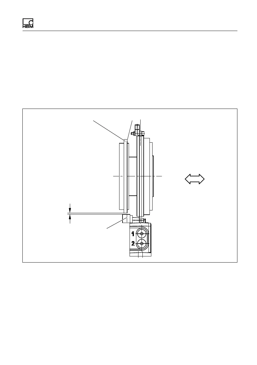
Axial alignment
There are markers on the sensor head for axial
alignment (orientation lines). When installed, the axial
inner surface of the pole ring should be exactly over the
axial orientation line. Divergence of up to ±1.5 mm is
permissible in measuring mode (total of static and
dynamic shift).
Pole ring
Axial inner surface
Axial orientation line
Radial distance
Axial alignment
Fig. 5.10 Position of the pole ring to the sensor head
Radial alignment
The rotor axis and the axis of the speed sensor must be
along a line at right angles to the stator platform. The
radial distance is critical for the radial alignment (see
Fig. 5.10). A vertical marker line on the head of the

 Loading...

