Electrical connection
T10FS A0785-150 HBM: public 53
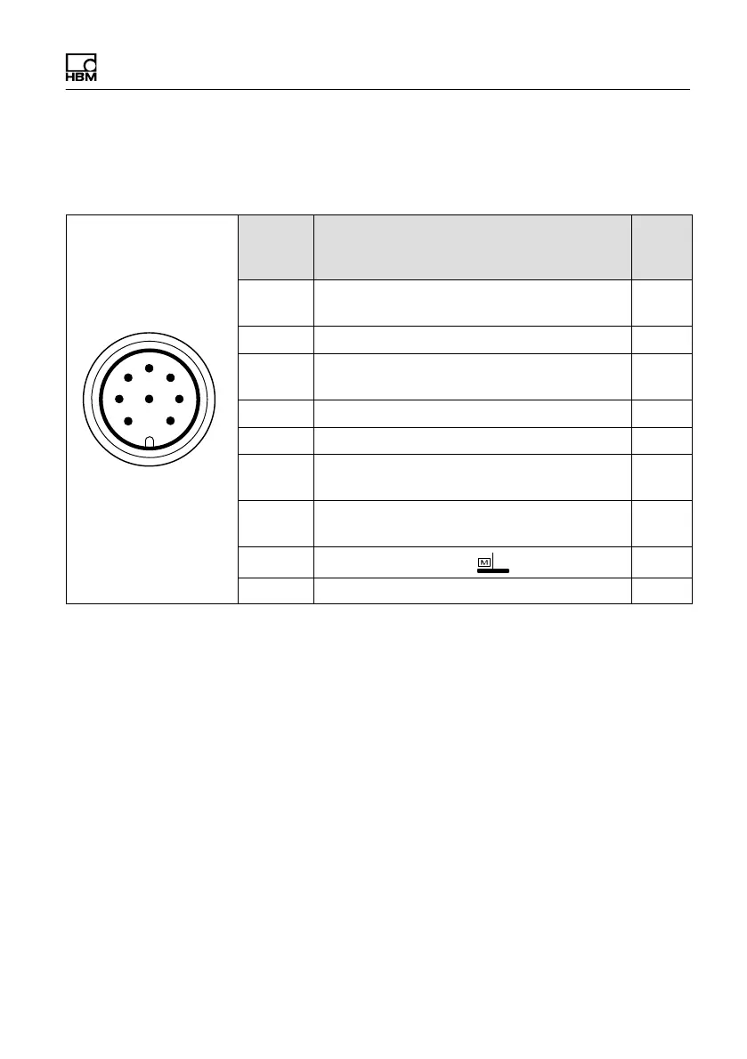
Assignment 2 connector 2
Speed measuring system with reference pulse
6
1
5
7
2
4
3
8
Binder 723
Top view
Conn.
Binder
Pin
Assignment Wire
color
1 Speed measurement signal (pulse string,
5 V
1)
; 0 °)
rd
2 Reference signal (1 pulse/rev., 5 V
1
) bu
3 Speed measurement signal (pulse string,
5 V
1
; phase‐shifted by 90 °)
2)
gy
4 Reference signal (1 pulse/rev., 5 V
1)
) bk
5 No function
6 Speed measurement signal (pulse string,
5 V
1
; 0 °)
wh
7 Speed measurement signal (pulse string,
5 V
1
; phase‐shifted by 90 °)
2
gn
8 Supply voltage zero ye
Shielding connected to housing ground
1)
RS422 complementary signals
2)
When switching to double frequency, static direction of rotation signal.


 To Next Page