EasyManuals Logo

HCFA Q Series User Manual

HCFA Q Series
88 pages
To Next Page IconTo Next Page
To Previous Page IconTo Previous Page
Page #13 background imageLoading...
Page #13 background image
11
Chapter 2 Part Names and Functions
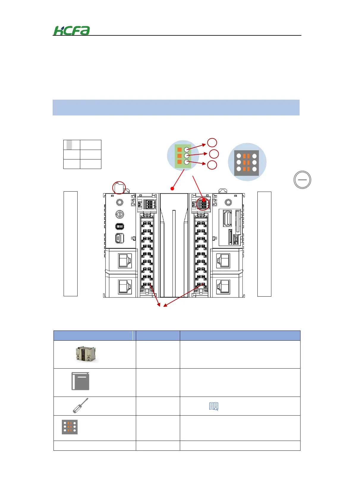
2-1 CPU unit
This section describes the model name, part names and functions for the CPU units.
2-1-1 Model name for CPU unit
After purchasing HCFA Q-series PLC, check if theres the following device and accessories before
unpacking.
Table 0-1 Q1 package details
Items
Quantity
Description
CPU unit
*1
Q1 series CPU unit
User Manual
*1
Q1 series user manual
Screwdriver
*1
For wiring
COM port Terminal block
*2
For RS232/RS485/CANopen wiring
*1
For providing 24VDC power
GND
0V
24V
Q 系列
说明书
Packaging
Terminal module
Attached to both sides
of CPU unit
Terminal module
Attached to both sides
of CPU unit
High-speed IO
On both sides of CPU unit
indicator
1
2
3
Terminal block
on the upper side
of CPU unit
Button cell
Mounted in the right side
cover of the CPU
Terminal block
Appendix1 Screwdriver spec.

Table of Contents

Questions and Answers:

Question and Answer IconNeed help?

Do you have a question about the HCFA Q Series and is the answer not in the manual?

HCFA Q Series Specifications

General IconGeneral
BrandHCFA
ModelQ Series
CategoryController
LanguageEnglish