62
After connecting the modules together according to the above steps, please
check the contact between the modules. Bad contact may cause failure, electric
shock amd module damage.
4-1-2 Precautions for module correction
Observe the following precautions when connecting unit or modules:
Make sure to turn off the power supply before connecting units or modules;
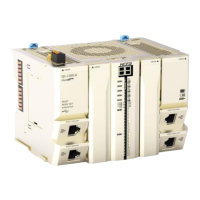
The AC power module must be installed on the left side of CPU unit and the metal sheet of mlodule
or CPU unit must be connected to the terminal module.
IO modules cannot be directly mounted to the right side of CPU unit, you need to add an EC
coupler.
4-2 Module wiring
This section mainly describdes the precautions and operation instructions about how to wire the CPU unit,
I/O devices and extension I/O modules.
4-2-1 Precautions on wiring
Do not touch the module or CPU unit immediately after cutting off the power. Failure
to do so may cause electric shock or burn.
Make sure that the voltages and currents that are input to the Units and modules are
within the specified ranges. Failure to do so may cause accidents or fire.
Up to 10 modules can be connected to
 Loading...