72
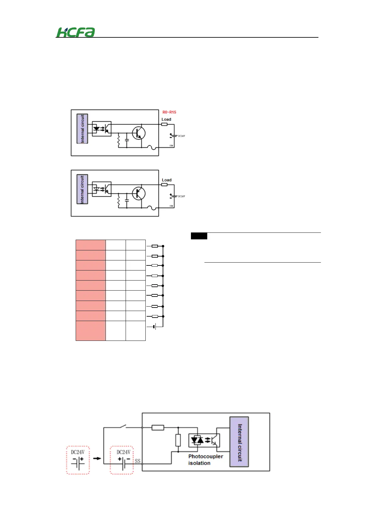
4-3-4 Digital output module wiring
As the remote extension module of Q-seires CPU unit, the module cannot work alone and needs to be
connected to the EC coupler or the right side of CPU unit. The wiring diagram is shown below:
、
4-3-5 Digital I/O module wiring
As the remote extension module of Q-seires CPU unit, the module cannot work alone and needs to be
connected to the EC coupler or the right side of CPU unit. The wiring diagram is shown below:
The digital output module(PNP) needs to be
customized. If necessary, pls contact HCFA
distributor.
*SS is short-circuited internally, and other channels are not connected. Take the channel I8-I15 as the example
*COM is short-circuited internally, and other channels are
not connected. Take the channel 8-15 as the example
Source output,high level is effective
Sink output,
 Loading...