Chapter 5 Maintenance and operation
5-1 RUN/STOP
This section will introduce the RUN and STOP operation of Q-series PLCs.
After writing the program to the controller, it is necessary to check the status of RUN/STOP dial switch, to
make sure that the CPU unit can work.
Table 0-1 RUN/STOP
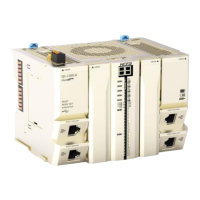
Make sure that the dial switch is on the right side and the
CPU is in the RUN state, otherwise it cannot work.
In the RUN state, the LED rotates like a rectangle.
In the stop state, the LED stands still.
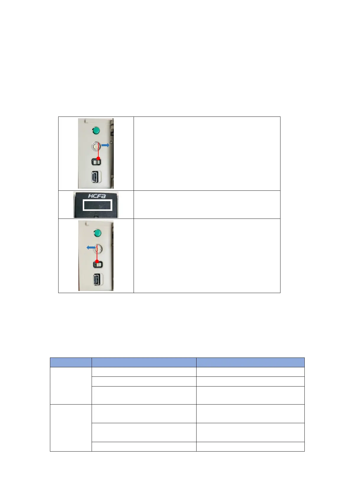
Dial the RUN/STOP switch to the left side to stop the CPU
operation. Users can stop the CPU operation by the upper
program.
5-2 Troubleshooting
5-2-1 CPU unit and extension module error
When some error occurs, the CPU unit cannot work and it cannot be connected to the CODESYS online
or commuinicate with HMI.
Table 0-2 CPU error and corresponding solutions
Power supply
error
(DC24V/AC
power module)
Connect the power correctly
Exceed the specified voltage range
Connect the suitable power
LED display 0E,overtemperature
Add the fan or ari-conditioner to reduce the ambient
temperature
Series CPU error and cannot be solved. Contact
HCFA distributor.
LED display 00,No program downloaded in CPU
Re-download the user program
RUN/STOP
Dial to right: RUN
 Loading...