74
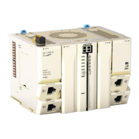
At the top of analog I/O module, 24VDC needed to be connected. The wiring diagram shown as below:
4-3-7 Analog output module wiring
The analog output module, as the remote extension module of the Q series CPU unit, cannot work alone
and needs to be connected to the EC coupler or the right side of the CPU unit. It supports both current
and voltage output. HCFA offers varieties of output ranges and the working range can be modified online
through SDO or COE, where the output signal can be directly used as the control signal of the motor or
drive.
At the top of analog I/O module, 24VDC needed to be connected. The wiring diagram shown as below:
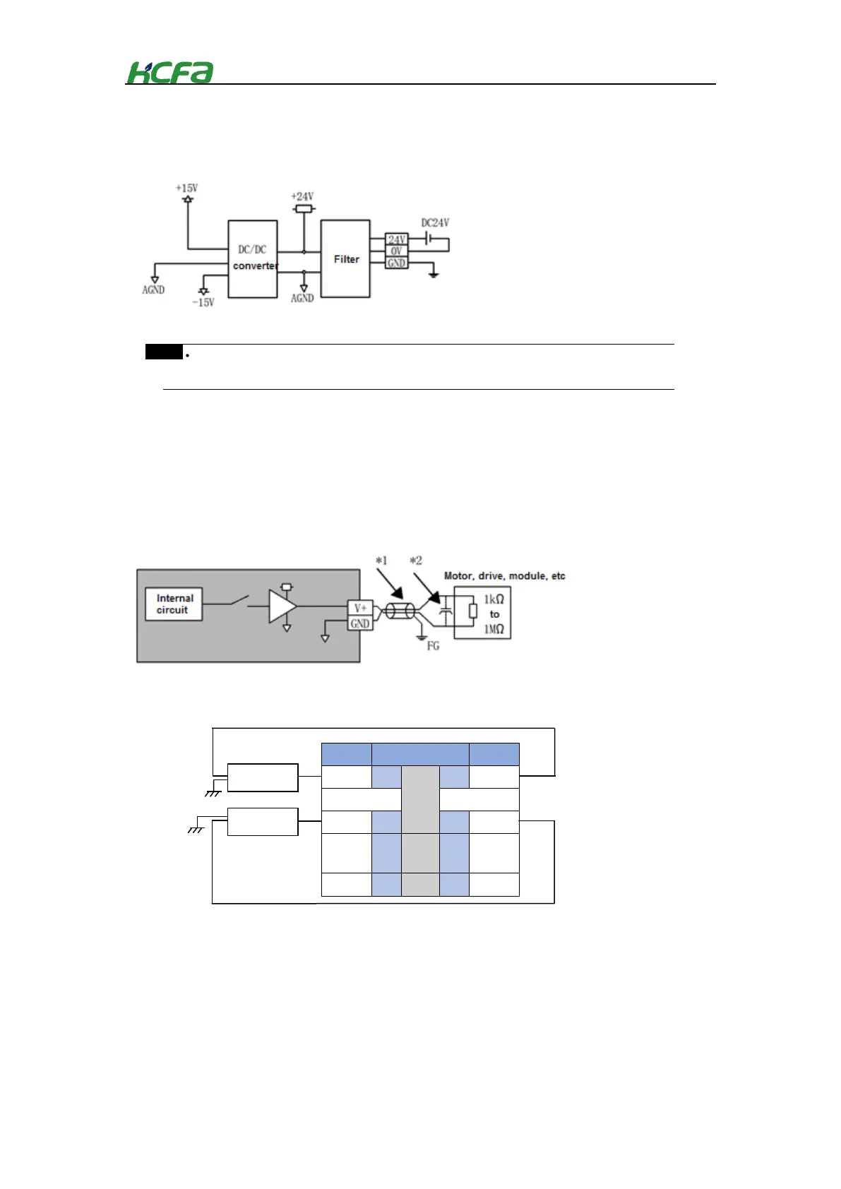
The analog signal cable adopts twisted-pair shielded wire
Equipotential is needed for the signal to be measured and “ AGND”
* In analog differential input, for inputs, take channel 1 as the example; for single-ended
input , take channel 2 as the example;for current inputs, take channel 1 as the example.
Internal circuit diagram of voltage output
Motor, drive,
module, etc.
Motor, drive,
module, etc.
 Loading...