68
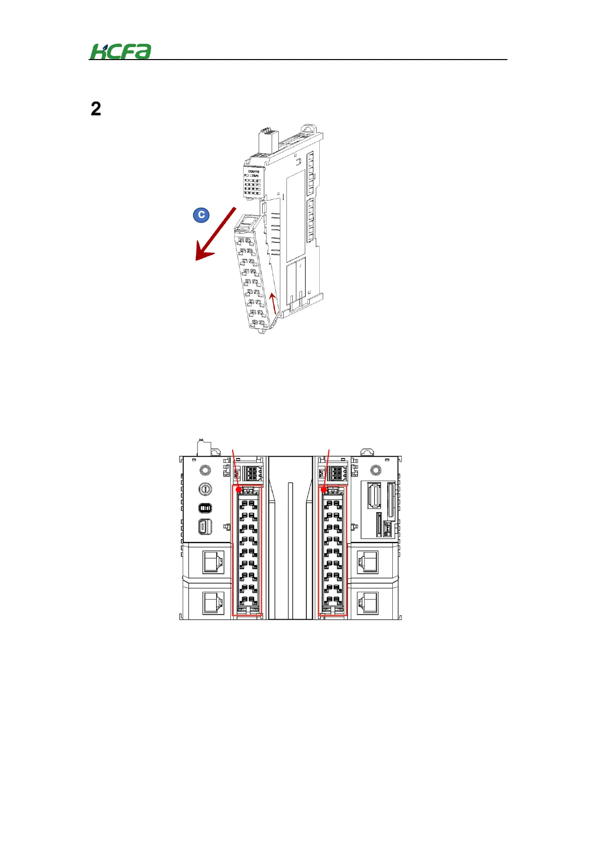
After unlocking the connector, remove the connector from the module in the “C” direction.
4-3 Module wiring
4-3-1 CPU unit high-speed I/O wiring
Q1 CPU unit is built-in 16-ch high-speed input and 16-ch high-speed output. And high-speed input
support source and sink input, as follows:
The I/O provided by the Q series CPU unit can be used either as high-speed input and output or as
general input and output. When the I/O is used as general input and output, it has both 16-point input and
16-point output. The wiring method is similar to that of general digital input and output. When the I/O is
used as high-speed input and output, the number of channels can be up to 8-ch input and 8-ch output.
Now the high-speed I/O provided by Q1 series PLC only support single-ended input and output. The
differential signal is under development in the following Q series PLC. Of course, the I/O wiring method
will affect the max. number of channels that are available. For detailed wiring mode, please refer to the
following instructions.
(Support PNP, NPN)
 Loading...